ME-403 · THEORY OF MACHINES/Unsolved PYQ Paper
ME-403 Theory of Machines - Jun 2026 Question Paper
Under each question, How to answer lists the points an answer should cover, outlined by CampusPrep from the syllabus. Check the details against your textbook.
-
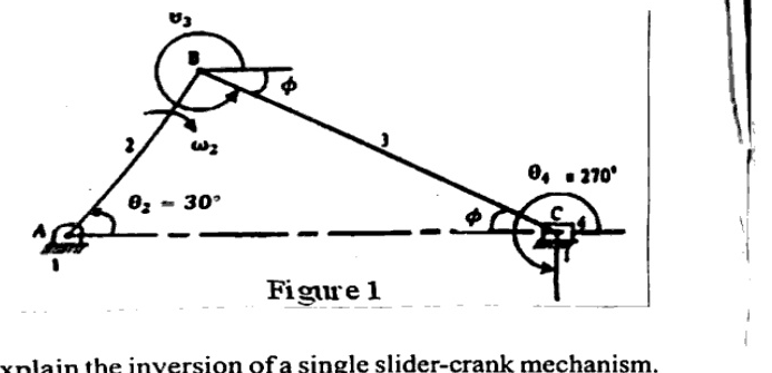
7 MarksaFigure 1 shows a slider crank mechanism. The crank and connecting rod are $150\,mm$ and $600\,mm$ long respectively and crank rotates at uniform speed of $100\,rpm$ (CW). Determine (a) Angular velocity and angular acceleration of the connecting rod
How to answer
- State crank length 150 mm, connecting rod 600 mm, speed 100 rpm CW and crank angle 30 deg from Figure 1
- Write velocity and acceleration loop equations / Klein's construction formulas
- Calculate angular velocity of connecting rod
- Calculate angular acceleration of connecting rod
-
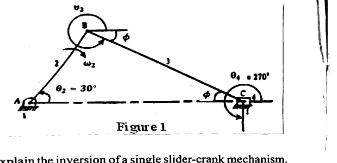
7 Marksb(b) Velocity and acceleration of piston.
How to answer
- Use crank kinematics and connecting rod angular motion from part (a)
- Calculate velocity of piston / slider C along line of stroke
- Calculate acceleration of piston using acceleration polygon / analytical formula
- State magnitude and direction
-
7 MarksaExplain the inversion of a single slider-crank mechanism. Describe any three inversions with neat sketches and their engineering applications.
How to answer
- Define inversion of kinematic chain by fixing different links
- Describe three inversions of single slider-crank with neat sketches
- Give constructional features of each inversion
- Give engineering applications e.g. reciprocating engine, Whitworth, slotted lever, hand pump
-
7 MarksbA slider-crank mechanism has a crank radius of $100\,mm$ and a connecting rod length of $450\,mm$. Determine the ratio of connecting rod length to crank radius.
How to answer
- Note crank radius 100 mm and connecting rod 450 mm
- Compute ratio n = l/r
- State numerical value 4.5
- Mention significance as obliquity ratio
-
7 MarksaDefine (i) base circle (ii) prime circle (iii) pressure angle with respect to cam profile. Why is it preferable to have a smaller pressure angle in cam design?
How to answer
- Define base circle as smallest circle from cam centre to cam profile
- Define prime circle as smallest circle from cam centre to pitch curve
- Define pressure angle between normal to pitch curve and follower motion direction
- Explain why smaller pressure angle reduces side thrust and improves force transmission
-
7 MarksbA radial cam is to give simple harmonic motion (SHM) to a knife edge follower with a lift of $50mm$. The rise takes place with SHM for $120^{\circ}$ of cam rotation. Then there is a dwell for $60^{\circ}$ and the return motion is also SHM for $90^{\circ}$ of cam rotation. The remaining $90^{\circ}$ of cam rotation is dwell. The minimum radius of cam is $50mm$. Calculate the maximum velocity and acceleration during the rise and return motion if the cam rotates at $200\,rpm$.
How to answer
- List SHM data: lift 50 mm, rise 120 deg, dwell 60 deg, return 90 deg, dwell 90 deg, min radius 50 mm, N=200 rpm
- Use SHM formulas $v_{max}=\pi h \omega/(2\beta)$, $a_{max}=\pi^2 h \omega^2/(2\beta^2)$
- Calculate max velocity and acceleration for rise
- Calculate max velocity and acceleration for return
-
7 Marksa$30\,KW$ of power is to be transmitted at $450\,rpm$ to a shaft with a speed ratio of $3.5$ through a $20^{\circ}$ stub spur gear drive. The load is steady and continuous. The centre distance is $400mm$ approximately. The pinion material is forged steel hardened to BHN 350 and the gear is made of cast steel hardened to BHN 250. (a) Design a gear drive for strength.
How to answer
- List power 30 kW, pinion 450 rpm, ratio 3.5, 20 deg stub, centre distance ~400 mm, BHN 350/250
- Determine module, teeth, face width from Lewis strength / beam strength
- Check proportions for steady continuous load
- Finalize gear drive dimensions for strength
-
7 Marksb(b) Check the design for dynamic load and wear.
How to answer
- Use Buckingham dynamic load formula
- Calculate wear load / Hertzian contact stress
- Compare allowable vs actual loads
- Conclude safety for dynamic and wear
-
7 MarksaExplain the construction and working principle of a single-plate clutch. https://www.rgpvonline.com
How to answer
- Draw labelled construction: flywheel, pressure plate, friction plate, springs, release mechanism
- Explain engagement by spring axial force and disengagement by clutch pedal
- Explain torque transmission by friction on single plate (two surfaces)
-
7 MarksbA single-plate clutch has an outer radius of $150\,mm$ and an inner radius of $75\,mm$. The axial force is $5\,kN$, and the coefficient of friction is $0.3$. Assuming uniform wear, determine the torque transmitted.
How to answer
- Note R=150 mm, r=75 mm, W=5 kN, mu=0.3, uniform wear
- Use mean radius $R_m=(R+r)/2$ and $T=n\mu W R_m$
- Calculate torque transmitted
- State result in N-m
-
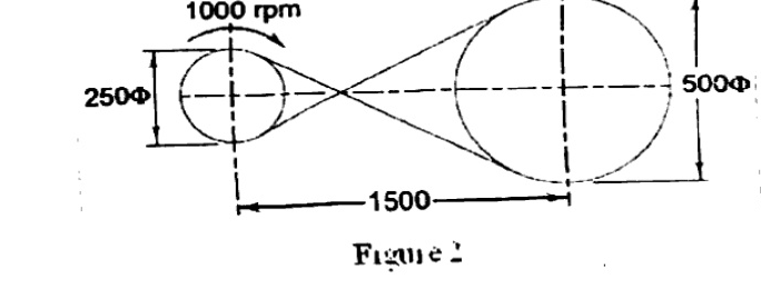
7 MarksaThe layout of a crossed flat leather belt drive is shown in Figure 2. The belt,$6mm$ thick, transmits $7.5kW$ and operates at a velocity of $13m/s$. The coefficient of friction between the belt and pulley surface is $0.3$ and the permissible tensile stress for the belt material is $1.75N/mm2$. The density of leather is $0.95g/cm^{3}$. Neglecting the sag and slip of the belt, calculate (a) The length and width of the belt.
How to answer
- Extract crossed belt geometry: D1=250 mm, D2=500 mm, C=1500 mm, thickness 6 mm
- Use crossed belt length $L=\pi(R+r)+2C+(R+r)^2/C$
- Apply power-tension relation with centrifugal tension and $\sigma_{allow}$
- Solve for width from $T_{max}=\sigma b t$
-
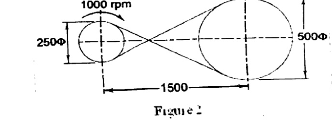
7 Marksb(b) Belt tensions on the tight and loose sides.
How to answer
- Use capstan ratio $T_1/T_2 = e^{\mu\theta}$ with crossed-belt contact angle
- Include centrifugal tension effect
- Solve tight-side and loose-side tensions
- Report $T_1$, $T_2$ values
-
7 MarksaState and explain the law of gearing. Discuss the importance of conjugate tooth profiles in ensuring constant velocity ratio.
How to answer
- State law of gearing: common normal passes through pitch point
- Derive constant angular velocity ratio condition
- Explain conjugate profiles e.g. involute
- Discuss importance for smooth uniform motion
-
7 MarksbExplain the concepts of static balancing and dynamic balancing. Discuss the balancing of rotating masses in the same plane and in different planes.
How to answer
- Define static balancing: resultant force zero
- Define dynamic balancing: resultant force and couple zero
- Explain balancing of masses in same plane
- Explain balancing in different planes with force and couple polygons
-
7 MarksaDefine a single degree of freedom (SDOF) system. Derive the equation of motion for an undamped free vibration system.
How to answer
- Define SDOF as system needing one coordinate
- Draw undamped spring-mass model with free-body diagram
- Apply Newton's second law $m\ddot{x}+kx=0$
- Obtain natural frequency form and solution
-
7 MarksbA spring of stiffness $10\,kN/m$ supports a mass of $25\,kg$. If the mass is displaced by $40\,mm$ and released from rest, determine the natural frequency, maximum velocity, and maximum acceleration.
How to answer
- Note k=10 kN/m, m=25 kg, amplitude 40 mm released from rest
- Compute $\omega_n=\sqrt{k/m}$ and $f_n=\omega_n/2\pi$
- Compute $v_{max}=A\omega_n$
- Compute $a_{max}=A\omega_n^2$
Go to where you left off?
Quick Add to Notes
Save questions, your own notes and screenshots into notes filed by unit. It takes a free account.
Create free accountHave an account? Log in
Notes Panel