ME-403 · THEORY OF MACHINES/Unsolved PYQ Paper
ME-403 Theory of Machines - Jun 2023 Question Paper
Under each question, How to answer lists the points an answer should cover, outlined by CampusPrep from the syllabus. Check the details against your textbook.
-
4 MarksaWhat is redundant degree of freedom of a mechanism?
How to answer
- Define redundant / passive degree of freedom as extra motion not affecting input-output relation
- Example e.g. roller of cam-follower having self rotation
- Distinguish from effective DOF
-
4 MarksbWhat is the degree of freedom of a mechanism? How is it determined?
How to answer
- Define DOF as number of independent inputs to define configuration
- State Kutzbach/Gruebler formula $F=3(l-1)-2j-h$
- Explain counting links, lower and higher pairs
-
3 MarkscWhat is Kutzback's criterion for degree of freedom of plane mechanisms? In what way is Gruebler's criterion different from it?
How to answer
- State Kutzbach criterion $F=3(l-1)-2j-h-F_r$
- State Gruebler criterion for single DOF planar with all lower pairs $3l-2j-4=0$
- Explain difference: Gruebler is special case with $h=0, F=1$
-
3 MarksdDefine Grashof's law. State how is it helpful in classifying the four-link mechanisms into different types.
How to answer
- Define Grashof's law $s+l \le p+q$ for continuous rotation
- State conditions for crank-rocker, double-crank, double-rocker
- Explain classification procedure with shortest link fixed/adjacent
-
14 MarksIn a mechanism shown in Fig.1, the angular velocity of the crank OA is $15 \text{ rad/s}$ and the slider at E is constrained to move at $2.5 \text{ m/s}$. The motion of both the sliders is vertical and the link BC is horizontal in the position shown. Determine the
- i)Rubbing velocity at B if the pin diameter is 15 mm.
- ii)Velocity of slider D.
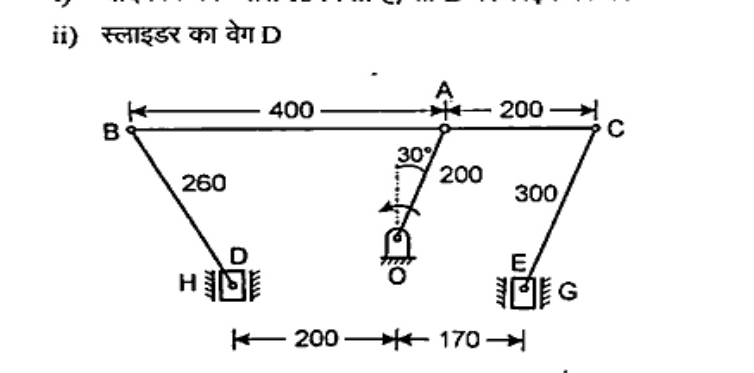
How to answer
- Draw configuration and velocity diagram / instantaneous centre method
- Compute velocity of A and relate to B-C link and sliders D, E
- Compute relative angular velocity at B for rubbing velocity $=r\cdot\omega_{rel}$ and velocity of D
-
7 MarksaExplain the D'Alembert's principle in brief.
How to answer
- State D'Alembert's principle: inertia force reverses effective motion
- Write $F - m a = 0$ for dynamic equilibrium
- Mention application to mechanism analysis
-
7 MarksbAn engine shaft running at $120 \text{ r.p.m.}$ is required to drive a machine shaft by means of a belt. The pulley on the engine shaft is of $2 \text{ m}$ diameter and that of the machine shaft is $1 \text{ m}$ diameter. If the belt thickness is $5 \text{ mm}$; determine the speed of the machine shaft, when
- i)There is no slip;
- ii)There is a slip of 3%.
How to answer
- Use belt speed ratio with thickness: $N_2/N_1 = (D_1+t)/(D_2+t)$
- Compute speed with no slip
- Reduce by 3% slip for second case
-
7 MarksaExplain with help of suitable sketches the inversions of double slider crank chain mechanism.
How to answer
- Define double slider crank chain
- Sketch three inversions: Scotch yoke, Oldham coupling, elliptical trammel
- Explain fixing of each link and motion obtained
-
7 MarksbFig:2, shows an epicyclic gear in which arm A is fixed to the shaft S, B is free to rotate on S and F is separately driven. A receives $7.5 \text{ kW}$ at $200 \text{ rpm}$ and F is driven in the same direction at $100 \text{ rpm}$. Determine the speed of B and the torque on its shaft.
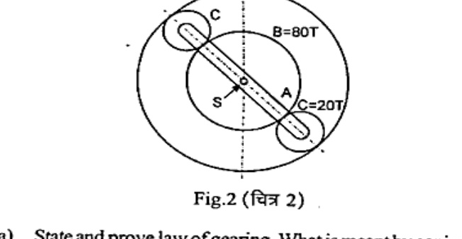
How to answer
- Tabulate teeth: F=120T, B=80T, C=20T and arm A
- Apply tabular method for epicyclic gear with arm fixed then add arm speed
- Solve for speed of B and torque from power $P=2\pi N T/60$
-
7 MarksaState and prove law of gearing. What is meant by conjugate gears? How is it satisfied by involute profile gear teeth?
How to answer
- State law of gearing: common normal passes through pitch point
- Prove with angular velocity ratio constant
- Define conjugate action and show involute satisfies it
-
7 MarksbAn engine running at $150 \text{ rpm}$ drives a line shaft by means of a belt. The engine pulley is $750 \text{ mm}$ diameter and the pulley on the line shaft is $450 \text{ mm}$. A $900 \text{ mm}$ diameter pulley on the line shaft drives a $150 \text{ mm}$ diameter pulley keyed to a dynamo shaft. Find the speed of the dynamo shaft when there is no slip.
How to answer
- Compute line shaft speed from engine pulley ratio
- Compute dynamo speed from second stage ratio $N_4 = N_3 D_3/D_4$
- Combine for overall velocity ratio
-
7 MarksaEstablish a formula for the frictional torque transmitted by a cone clutch.
How to answer
- Consider frustum element and uniform pressure/wear assumption
- Integrate frictional moment $dT = \mu p 2\pi r^2 dr /\sin\alpha$
- Obtain $T = (2/3)\mu W (R^3-r^3)/(R^2-r^2)/\sin\alpha$
-
7 MarksbDefine the following terms as applied to cam with a neat sketch:
- i)Base circle
- ii)Pitch circle
- iii)Pressure angle
- iv)Stroke of the follower
How to answer
- Draw cam with base, pitch circles, pressure angle and stroke marked
- Define each term with reference to diagram
- Distinguish base vs prime vs pitch circle
-
14 MarksA cam rotating clockwise at a uniform speed of $100 \text{ r.p.m.}$ is required to give motion to knife-edge follower as below:
- a)Follower to move outwards through 25 mm during 120° of cam rotation,
- b)Follower to dwell for the next 60° of cam rotation.
- c)Follower to return to its starting position during next 90° of cam rotation.
- d)Follower to dwell for the rest of the cam rotation.
How to answer
- Note data: $N=100$ rpm, $S=25$ mm, angles $120^\circ/60^\circ/90^\circ$
- Use uniform acceleration-retardation formulas $v_{max}=2S\omega/\theta$, $a=4S\omega^2/\theta^2$
- Compute values for outstroke and return stroke separately
-
7 MarksaA $20^{\circ}$ involute pinion with $20$ teeth drives a gear having $60$ teeth. Module is $8 \text{ mm}$ and addendum of each gear is $10 \text{ mm}$.
- i)State whether interference occurs or not. Give reasons.
- ii)Find the length of path of approach and arc of approach if pinion is the driver.
How to answer
- Compute pitch radii, addendum radii and path of approach/recess
- Check interference condition $Addendum > \sqrt{R^2 - R^2\cos^2\phi} - R\sin\phi$
- Compute arc of approach $=$ path$/\cos\phi$
-
7 MarksbA simple band brake is operated by a lever of length $500 \text{ mm}$. The brake drum has a diameter of $500 \text{ mm}$ and the brake band embraces $5/8$ of the circumference. One end of the band is attached to the fulcrum of the lever while the other end is attached to a pin on the lever $100 \text{ mm}$ from the fulcrum. If the effort applied to the end of the lever is $2 \text{ kN}$ and the coefficient of friction is $0.25$, find the maximum braking torque on the drum.
How to answer
- Draw lever-drum with tensions $T_1,T_2$ and $T_1/T_2=e^{\mu\theta}$
- Take moment about fulcrum to find tight-side tension from effort $2$ kN
- Compute braking torque $(T_1-T_2)r$ for both rotation directions and take maximum
Go to where you left off?
Quick Add to Notes
Save questions, your own notes and screenshots into notes filed by unit. It takes a free account.
Create free accountHave an account? Log in
Notes Panel