EX-405 · Control System/Unsolved PYQ Paper
EX-405 Control System - Jun 2025 Question Paper
Under each question, How to answer lists the points an answer should cover, outlined by CampusPrep from the syllabus. Check the details against your textbook.
-
7 MarksaFor a given rotational system, obtain the electrical analogous systems based on inverse and direct analogous methods.
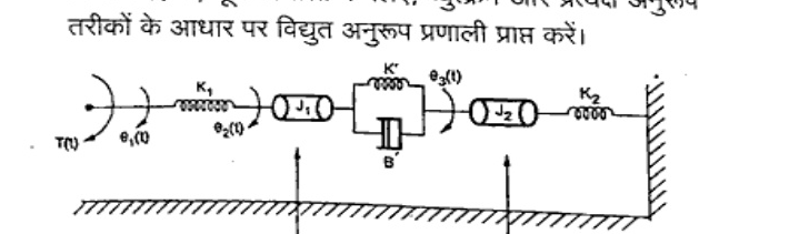
How to answer
- Write differential equations for rotational system with inertias J1, J2, stiffness K1, K2, K', damping B1, B2, B'
- Force-voltage (direct) analogy: torque->voltage, angular velocity->current, J->L, B->R, K->1/C
- Force-current (inverse) analogy: torque->current, angular velocity->voltage, J->C, B->1/R, K->1/L
- Draw both analogous electrical networks with loops/nodes corresponding to theta1, theta2, theta3
-
7 MarksbUsing Mason's gain formula, find the gain of the following system in figure below.
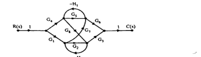
How to answer
- Identify forward paths Pk and individual loops from signal flow graph with gains G1-G7, H1, H2
- Find non-touching loops and compute graph determinant Delta = 1 - sum L1 + sum L2 ...
- Compute path cofactors Delta_k for each forward path
- Apply Mason's formula T = (1/Delta) sum Pk Delta_k to get C(s)/R(s)
-
7 MarksaDerive transfer function of A.C. servomotor stating the assumption made.
How to answer
- State assumptions: linear magnetic circuit, negligible saturation, two-phase balanced operation, constant rotor resistance
- Write torque-speed characteristics and motor equations for control and reference phases
- Linearize around operating point to get transfer function Theta_m(s)/E(s)
- Give final form Km/(s(Tm s+1)) and define motor gain and time constant
-
7 MarksbDerive the relationship maximum overshoot and damping ratio of a second order system. Draw the graph or overshoot versus damping ratio.
How to answer
- Write step response of standard second-order system with damping ratio zeta
- Differentiate to find peak time and peak value c(tp)
- Obtain Mp = exp(-pi*zeta/sqrt(1-zeta^2)) and % overshoot formula
- Sketch Mp vs zeta decaying curve from 1 to 0
-
7 MarksaThe Fig. shows PD controller used for the system. Determine the value of $T_d$ so that system will be critically damped. Calculate its settling time.
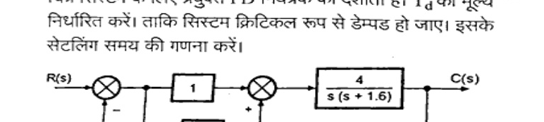
How to answer
- Reduce PD block (1+sTd) in forward path with plant 4/(s(s+1.6)) to closed-loop characteristic equation
- Apply critical damping condition zeta=1 to solve for Td
- Compute natural frequency wn and settling time ts = 4/(zeta*wn)
- State numerical values of Td and ts
-
7 MarksbDerive the expressions for static error coefficients? How these coefficients are useful in determining steady state error? State the limitations of static error coefficient method.
How to answer
- Define position, velocity, acceleration error constants Kp, Kv, Ka as limits of G(s)
- Derive ess for step, ramp, parabolic inputs in terms of Kp, Kv, Ka
- Explain use for type 0,1,2 systems to predict finite/zero/infinite error
- State limitations: only for unity feedback, stable systems, standard inputs
-
7 MarksaFor a unity feedback system, $$G(s) = \frac{K}{s(1+0.4s)(1+0.25s)},$$ find range of values of K, marginal value of K and frequency of sustained oscillations.
How to answer
- Form closed-loop characteristic equation 0.1 s^3 + ... + K = 0
- Apply Routh-Hurwitz criterion to get stability condition on K
- Set row of zeros for marginal K and solve auxiliary equation for oscillation frequency
- Report range 0<K<Kmar, Kmar and omega_n
-
7 MarksbSketch the complete root locus with approximate indication of breakaway points. Comment on the stability.
How to answer
- Determine poles, zeros, asymptotes, centroid and real-axis segments
- Calculate breakaway points from dK/ds=0 and angle of departure if complex poles
- Sketch root locus branches approaching asymptotes/infinity
- Comment on stability range of K from crossing of imaginary axis
-
7 MarksaExplain the procedure of obtaining the value of K for specified damping ratio $\xi$ from the root locus.
How to answer
- Draw constant zeta line at angle theta = cos^-1(zeta) from negative real axis
- Intersection of this line with root locus gives closed-loop poles for required zeta
- Apply magnitude condition |K G(s)H(s)|=1 at that point to find K
- Verify with calculation steps
-
7 MarksbA unity feedback control system has $$G(s) = \frac{80}{s(s+2)(s+20)}$$ Drawn the Bode Plot. Determine G.M. P.M. $\omega_{gc}$ and $\omega_{pc}$ Comment on the stability.
How to answer
- Rewrite G(s) in time-constant form and identify corner frequencies 2 and 20 rad/s
- Draw magnitude (dB) and phase asymptotes and actual Bode plot
- Find gain crossover wgc, phase crossover wpc, GM and PM from plot
- Comment stable if GM>0 dB and PM>0 degrees
-
7 MarksaFor a feedback control system $$G(s)H(s) = \frac{40}{(s+4)(s^2+2s+2)}$$ Find gain margin and stability from Nyquist plot.
How to answer
- Map Nyquist contour and plot G(jw)H(jw) for w from 0 to infinity
- Find phase crossover where plot crosses negative real axis
- Compute gain margin GM = 1/|G(jwpc)H(jwpc)|
- Apply Nyquist stability criterion Z = P - N to comment on stability
-
7 MarksbWhat is Polar plot? Explain polar plots for Type 0, 1 and 2 systems.
How to answer
- Define polar plot as G(jw) magnitude vs phase for w 0 to infinity
- Sketch Type 0 starting on positive real axis ending at origin
- Sketch Type 1 starting at -90 deg infinity ending at origin
- Sketch Type 2 starting at -180 deg infinity ending at origin
-
7 MarksaA unit step input is applied to a unity feedback control system whose open loop transfer function is given by. $$G(s) = \frac{K}{s(sT+1)}$$ Determine the values of K and T given that maximum overshoot as 26 % and resonant frequency $\omega_r = 8 rad / s$. Calculate the resonance peak $M_r$.
How to answer
- Relate % overshoot 26% to damping ratio zeta via Mp formula
- Relate resonant frequency wr=8 rad/s and bandwidth to wn and zeta
- Solve two equations for K and T using standard form K/T/(s^2+s/T+K/T)
- Compute resonant peak Mr = 1/(2 zeta sqrt(1-zeta^2))
-
7 MarksbDefine a different steps of Lag-lead compensation network.
How to answer
- State need for lag-lead compensation and its transfer function form
- List steps: determine required phase lead, place zero-pole, design lag section
- Mention selection of beta, time constants and verification via Bode/root locus
- Conclude with implementation check
Go to where you left off?
Quick Add to Notes
Save questions, your own notes and screenshots into notes filed by unit. It takes a free account.
Create free accountHave an account? Log in
Notes Panel