CE-403 · Structural Analysis-I/Unsolved PYQ Paper
CE-403 Structural Analysis-I - Jun 2024 Question Paper
Under each question, How to answer lists the points an answer should cover, outlined by CampusPrep from the syllabus. Check the details against your textbook.
-
7 MarksaWhat is the principle of virtual work? Explain its application to flexural members.
How to answer
- Define principle of virtual work for deformable bodies
- Expression for virtual work by external and internal forces
- Application to flexural members: deflection calculation using dummy unit load
- Integral form with M*m/EI and procedure steps
-
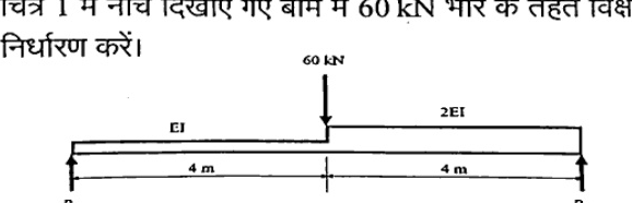
7 MarksbDetermine the deflection under 60 kN load in the beam shown below in Fig. 1.
How to answer
- Determine reactions RA, RB for beam with EI and 2EI segments
- Write bending moment equations M and virtual m for unit load at 60 kN point
- Apply virtual work / unit load integral deflection = integral M*m/EI dx
- Compute numerical deflection value and direction
-
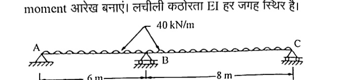
7 MarksaAnalyze the continuous beam ABC as shown in Fig. 2, using three moment theorem and draw bending moment diagram. Flexural rigidity EI is constant throughout.
How to answer
- Apply Clapeyron's three moment equation to spans AB and BC with UDL
- Calculate free bending moments and support moments MA=0, MB, MC=0
- Find reactions and draw shear force diagram
- Draw bending moment diagram showing hogging at B and sagging maxima
-
7 MarksbWhat do you understand by indeterminacy? Also explain static and kinematic indeterminacy?
How to answer
- Define indeterminacy / degree of indeterminacy
- Static indeterminacy: external and internal with formulas
- Kinematic indeterminacy: joint displacements/degrees of freedom
- Examples for beams, frames, trusses
-
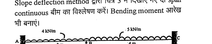
7 MarksaAnalyse the two span continuous beam shown in Fig. 3. By slope deflection method. Also draw bending moment diagram.
How to answer
- Compute fixed end moments for spans AB (3 m, 4 kN/m) and BC (4 m, 5 kN/m) with fixed ends
- Write slope deflection equations with zero slopes at fixed ends A and C
- Apply equilibrium at B to solve rotation theta_B
- Find end moments and draw bending moment diagram
-
7 MarksbExplain the column analogy method for the analysis of a beam with suitable example.
How to answer
- State principle of column analogy: analogous column with width EI
- Load on analogy as M/EI diagram and stress as moment
- Procedure to find indeterminate moment and shear
- Illustrate with suitable fixed beam example
-
14 MarksA two hinged parabolic arch of span 'L' and rise 'h' carries a concentrated load 'W' at the crown. Determine the expression for horizontal thrust developed at support.
How to answer
- Assume parabolic profile y = 4h x(L-x)/L^2
- Use Castigliano's / virtual work condition for zero horizontal displacement
- Evaluate integrals of M*m/EI to get horizontal thrust H
- Result H = W*L/(8h) for crown point load (with rib shortening neglected)
-
14 MarksA light cable is supported at two points 20 m apart which are at the same level. The cable supports three concentrated loads of magnitudes 40 kN, 30 kN and 20 kN at a distance of 5 m, 10 m and 15 m from left support respectively. The deflection at first point is found to be 0.8 m. Determine the tension in the different segments and total length of the cable.
How to answer
- Use equilibrium to relate horizontal component H and vertical reactions
- Use given deflection 0.8 m at first load to find H
- Compute segment tensions T = sqrt(H^2+V^2) for each segment
- Estimate total cable length from inclined lengths
-
14 MarksCalculate the ordinates of influence line for moment at mid-span of span BC for the beam shown in Fig. 4, at 1 m interval and draw influence line diagram. Assume moment of inertia to be constant throughout.

How to answer
- Identify beam ABC with spans 4 m each and mid-point D in BC
- Use Muller-Breslau or equilibrium to get ILD ordinates at 1 m intervals
- Tabulate ordinates at points 1-6 and supports
- Plot influence line diagram for moment at mid-span of BC
-
14 MarksDefine the following terms:
- i)Muller-Breslau principles
- ii)Castigliano's first and second theorem
- iii)Strain energy method
- iv)Influence line diagram of a beam
How to answer
- State Muller-Breslau principle for ILD
- State Castigliano's first and second theorems with formulas
- Define strain energy method for deflection
- Define influence line diagram for beam with example
-
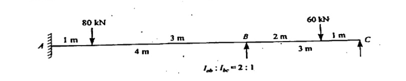
14 MarksA continuous beam ABC consists of two spans AB = 4 m and BC = 3 m, the end A being fixed. The span AB carries a point load of 80 kN at 1 m from A while the span BC carries a point load of 60 kN at 1 m from C, $I_{ab} : I_{bc} = 2:1$. Find the support moment and draw bending moment diagram using moment distribution method.
How to answer
- Compute distribution factors at B using I_ab:I_bc = 2:1 and stiffness with fixed A
- Compute fixed end moments for point loads 80 kN and 60 kN
- Carry out moment distribution cycles to get support moments
- Draw bending moment diagram with free and support moments
Go to where you left off?
Quick Add to Notes
Save questions, your own notes and screenshots into notes filed by unit. It takes a free account.
Create free accountHave an account? Log in
Notes Panel