ME-304 · Strength of Material/Unsolved PYQ Paper
ME-304 Strength of Material - Dec 2024 Question Paper
Under each question, How to answer lists the points an answer should cover, outlined by CampusPrep from the syllabus. Check the details against your textbook.
-
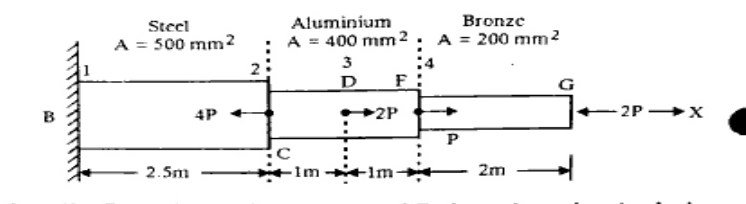
7 MarksaA bar is made-up of three portions of three different materials-steel, aluminum and bronze. Its one end is fixed and it is axially loaded as shown in the figure. Find the maximum value of P that will not exceed a stress in steel of 140 MPa, in aluminum of 90 MPa and in bronze of 100 MPa.
How to answer
- Draw free body diagrams or determine internal axial forces in each segment in terms of P
- Express stress in each material segment as $\sigma = P_{internal} / A$
- Set up allowable stress inequality for steel: $\sigma_{steel} \le 140\text{ MPa}$
- Set up allowable stress inequality for aluminium: $\sigma_{alum} \le 90\text{ MPa}$
- Set up allowable stress inequality for bronze: $\sigma_{bronze} \le 100\text{ MPa}$
- Take the minimum resulting value of P to satisfy all constraints simultaneously
-
7 MarksbDefine Thermal stresses and Poisson's ratio. And also write the relationship between shear modulus and Young's modulus of elasticity.
How to answer
- Definition of thermal stress developed due to restriction of thermal expansion/contraction ($\\sigma = E \alpha \Delta T$)
- Definition of Poisson's ratio as lateral strain over longitudinal strain ($\nu = -\frac{\epsilon_{lat}}{\epsilon_{long}}$)
- State the relationship: $E = 2G(1 + \nu)$ relating Young's modulus $E$, shear modulus $G$, and Poisson's ratio $\nu$
-
7 MarksaWhat is Macaulay's method of beam deflection analysis? What are its advantages over the direct integration method?
How to answer
- Concept of Macaulay's method using bracket/singularity functions for discontinuous loading
- Standard bending moment expression formulation: $EI \frac{d^2y}{dx^2} = M(x)$
- Single continuous equation throughout the length of the beam
- Advantages: Only two constants of integration for the entire beam instead of separate constants for each section
- Simplifies evaluation of boundary conditions
-
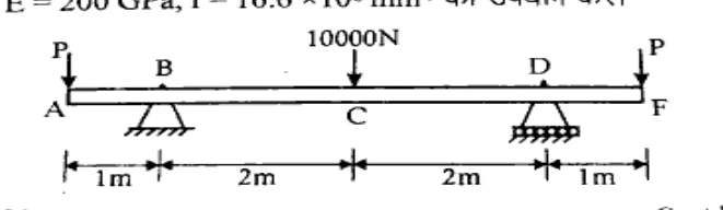
7 MarksbFor the beam and loading shown in the figure, determine the magnitude of the force P for which the deflection is zero at end A. Use $\text{E} = 200\text{ GPa}$, $\text{I} = 16.6 \times 10^6\text{ mm}^4$.
How to answer
- Determine support reactions at B and D in terms of P and the 10,000 N load
- Write the Macaulay's bending moment expression $M(x)$ choosing origin at end A
- Integrate twice to obtain expressions for slope $EI \frac{dy}{dx}$ and deflection $EI y$
- Apply boundary conditions: $y = 0$ at $x = 1\text{ m}$ (support B) and at $x = 5\text{ m}$ (support D) to find integration constants
- Set $y(0) = 0$ (deflection at A = 0) to solve for P
-
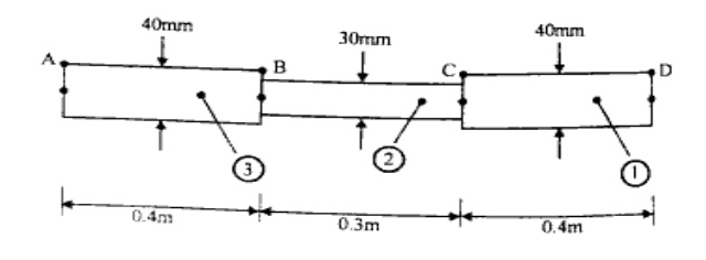
7 MarksaThe stepped circular shaft shown in figure has been used as a machine part component in which section A, C and D have torques applied to give the specified rotation as : $\phi_{\text{A}} = -1^\circ, \phi_{\text{C}} = \frac{1^\circ}{2}$ and $\phi_{\text{D}} = 1^\circ$. Assume $\text{G} = 75\text{ GPa}$ Find: i) The values of torque at sections A, C and D which causes the specified angular rotation. ii) The angle of twist at section B. iii) The maximum shear stress in each of the three shaft segments.
How to answer
- Calculate polar moment of inertia $J$ and torsional stiffness $k_t = \frac{GJ}{L}$ for each segment
- Use relative rotations: $\Delta\phi_{CD} = \phi_D - \phi_C$, $\Delta\phi_{BC} = \phi_C - \phi_B$, etc.
- Set up equilibrium and compatibility equations to find torques at A, C, D and rotation $\phi_B$
- Determine internal torque in each of the three segments
- Compute maximum shear stress using $\tau = \frac{T r}{J}$ for each segment
-
7 MarksbDeduce the expressions for maximum stresses in solid and hollow shafts.
How to answer
- State the torsion equation: $\frac{T}{J} = \frac{\tau}{R}$
- For solid shaft: $J = \frac{\pi D^4}{32}$, $R = \frac{D}{2}$, derive $\tau_{max} = \frac{16T}{\pi D^3}$
- For hollow shaft: $J = \frac{\pi (D^4 - d^4)}{32}$, $R = \frac{D}{2}$, derive $\tau_{max} = \frac{16TD}{\pi (D^4 - d^4)}$
-
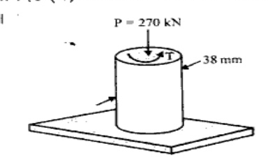
7 MarksaA solid-steel-circular shaft, for which the yield strength is $\sigma_{\text{Y}} = 290\text{ MPa}$, is subjected to an axial compressive load P and a torque T. Determine the magnitude of the torque T for which yield occurs when $\text{P} = 270\text{ kN}$ according to (a) maximum shear stress criterion (b) maximum-distortion-energy criterion.
How to answer
- Calculate direct axial compressive stress: $\sigma_x = -\frac{P}{\pi d^2 / 4}$
- Express shear stress due to torque: $\tau_{xy} = \frac{16T}{\pi d^3}$
- Part (a) Maximum Shear Stress Criterion (Tresca): $\sqrt{\sigma_x^2 + 4\tau^2} = \sigma_Y$, solve for $T$
- Part (b) Maximum Distortion Energy Criterion (von Mises): $\sigma_x^2 + 3\tau^2 = \sigma_Y^2$, solve for $T$
-
7 MarksbDiscuss the Maximum Distortion Energy Theory for predicting the failure of materials under complex loading conditions. Compare its application and limitations with respect to ductile and brittle materials.
How to answer
- Statement and concept of Von Mises / Maximum Distortion Energy Theory
- Mathematical formulation: $\frac{1}{2}[(\sigma_1-\sigma_2)^2 + (\sigma_2-\sigma_3)^2 + (\sigma_3-\sigma_1)^2] \le \sigma_y^2$
- Application to ductile materials: excellent agreement with experimental data under general multiaxial stress states
- Limitations for brittle materials: poor prediction because brittle failure occurs by cleavage/tensile fracture rather than shear distortion
-
7 MarksaA $50\text{ mm}$ by $100\text{ mm}$ timber is used as a column with fixed ends. Determine : i) The minimum length at which Euler's formula can be used if $\text{E} = 10\text{ GPa}$ and the proportional limit is $30\text{ MPa}$. ii) The central load that can be carried with a factor of safety 2 if the length is $2.5\text{ m}$.
How to answer
- Calculate $I_{min} = \frac{100 \times 50^3}{12}$ and radius of gyration $k_{min} = \frac{50}{\sqrt{12}}$
- For both ends fixed: $L_e = \frac{L}{2}$
- Equate critical stress to proportional limit: $\sigma_{cr} = \frac{\pi^2 E}{(L_e / k_{min})^2} = 30\text{ MPa}$ to find minimum $L$
- For $L = 2.5\text{ m}$, check if Euler's formula applies, calculate $P_{cr} = \frac{4\pi^2 E I_{min}}{L^2}$
- Calculate allowable load: $P_{safe} = \frac{P_{cr}}{\text{FOS}}$
-
7 MarksbCompare the crippling loads given by Rankine's and Euler's formulae for tubular strut $225\text{ cm}$ long having outer and inner diameter of $37.5\text{ mm}$ and $32.5\text{ mm}$ respectively loaded through pin joints at both ends. Take yield stress as $315\text{ MPa}$; $a = \frac{1}{7500}$ and $\text{E} = 200\text{ GPa}$. If elastic limit for the material is taken as $200\text{ MPa}$, below what length of the strut does the Euler formula ceases to apply.
How to answer
- Calculate area $A = \frac{\pi}{4}(D^2 - d^2)$, moment of inertia $I = \frac{\pi}{64}(D^4 - d^4)$, and radius of gyration $k = \sqrt{I/A}$
- Calculate Euler's load: $P_E = \frac{\pi^2 E I}{L^2}$ (pin-jointed, $L_e = L$)
- Calculate Rankine's load: $P_R = \frac{\sigma_c A}{1 + a (L/k)^2}$ and compare with $P_E$
- Determine slenderness ratio limit using $\frac{\pi^2 E}{\lambda^2} = \sigma_e = 200\text{ MPa}$
- Calculate limiting length $L = \lambda \cdot k$ below which Euler's formula does not apply
-
7 MarksaDerive an expression for the normal stress and shear stress on a plane inclined at $\theta$ to the vertical axis in a biaxial stress system with the shear. Also prove that the sum of the normal stress on any two mutually perpendicular Planes is always constant.
How to answer
- Draw an inclined wedge element under general 2D stress ($\sigma_x, \sigma_y, \tau_{xy}$)
- Resolve forces along the normal and tangential directions of the inclined plane
- Derive normal stress: $\sigma_\theta = \frac{\sigma_x + \sigma_y}{2} + \frac{\sigma_x - \sigma_y}{2} \cos 2\theta + \tau_{xy} \sin 2\theta$
- Derive shear stress: $\tau_\theta = -\frac{\sigma_x - \sigma_y}{2} \sin 2\theta + \tau_{xy} \cos 2\theta$
- Substitute $\theta + 90^\circ$ for the perpendicular plane and show $\sigma_\theta + \sigma_{\theta+90^\circ} = \sigma_x + \sigma_y = \text{constant}$
-
7 MarksbA simply supported cast-iron square beam of $1000\text{ mm}$ length and $20\text{ mm} \times 20\text{ mm}$ in section fails on applying a load of $380\text{ N}$ at the mid span. Find the maximum uniformly distributed load that can be applied safely to a $38\text{ mm}$ wide, $72\text{ mm}$ deep and $1.4\text{ m}$ long cantilever made of the same material.
How to answer
- Calculate maximum bending moment for simply supported beam: $M_1 = \frac{W_1 L_1}{4} = \frac{380 \times 1}{4} = 95\text{ N}\cdot\text{m}$
- Calculate section modulus $Z_1 = \frac{20 \times 20^2}{6} = 1333.33\text{ mm}^3$
- Calculate failure bending stress (modulus of rupture): $\sigma_f = \frac{M_1}{Z_1}$
- Calculate section modulus of cantilever: $Z_2 = \frac{b_2 d_2^2}{6} = \frac{38 \times 72^2}{6} = 32832\text{ mm}^3$
- Set maximum bending moment of cantilever under UDL $M_2 = \frac{w L_2^2}{2} = \sigma_f Z_2$ and solve for $w$
-
7 MarksaShow that a body subjected to a pure shear is also acted upon by tensile and compressive stresses as well.
How to answer
- Represent state of pure shear on an element with shear stress $\tau$ and $\sigma_x = \sigma_y = 0$
- Use transformation equations for normal stress at angle $\theta$: $\sigma_\theta = \tau \sin 2\theta$
- Show that at $\theta = 45^\circ$, $\sigma = +\tau$ (tensile stress)
- Show that at $\theta = 135^\circ$ (or $-45^\circ$), $\sigma = -\tau$ (compressive stress)
- Sketch Mohr's circle or the rotated element showing equal mutually perpendicular tensile and compressive stresses
-
7 MarksbA steel rod of $16\text{ mm}$ diameter and $3\text{ m}$ length passes through a copper tube of $50\text{ mm}$ external and $40\text{ mm}$ internal diameter and of the same length. The tube is closed at each end with the help of $30\text{ mm}$ thick steel plates which are tightened by nuts till the length of the copper tube is reduced by $0.6\text{ mm}$ the temperature of the whole assembly is then raised by $56^\circ\text{C}$. Determine the stresses in the steel and copper before and after the rise of temperature. Assume that thickness of the steel plates at the ends do not change during tightening of the nuts. $\text{E}_s = 210\text{ GPa}; \text{E}_c = 100\text{ GPa}; \alpha_s = 12 \times 10^{-6}/^\circ\text{C};$ $\alpha_c = 17 \times 10^{-6}/^\circ\text{C}$.
How to answer
- Calculate cross-sectional areas: $A_s = \frac{\pi}{4}(16)^2$, $A_c = \frac{\pi}{4}(50^2 - 40^2)$
- Before temperature rise: strain in copper is $\epsilon_c = \frac{0.6}{3000}$, so $\sigma_c = E_c \epsilon_c$ (compressive)
- Equilibrium of forces: $P_s = P_c \implies \sigma_s = \sigma_c \frac{A_c}{A_s}$ (tensile)
- Due to temperature rise $\Delta T = 56^\circ\text{C}$: thermal strain difference $(\alpha_c - \alpha_s)\Delta T$ causes additional compression in copper and tension in steel
- Superimpose initial tightening stresses and thermal stresses to obtain final stresses in steel and copper
-
7 MarksaWhat is Crippling load? Give the effective length of columns when both ends hinged and when both ends fixed.
How to answer
- Define crippling (buckling) load as the maximum axial compressive load a column can support just before it fails by lateral deflection/buckling
- Explain the concept of effective length $L_e$ based on points of inflection / zero moment
- State effective length when both ends are hinged/pinned: $L_e = L$
- State effective length when both ends are fixed: $L_e = \frac{L}{2}$
-
7 MarksbExplain the theory of failure for (i) Ductile materials (ii) Brittle materials.
How to answer
- Discuss Ductile Materials: failure is governed by yielding / shear slip
- Describe Tresca (Maximum Shear Stress Theory) and Von Mises (Maximum Distortion Energy Theory) with failure criteria equations
- Discuss Brittle Materials: failure is governed by separation / cleavage fracture due to normal stress
- Describe Rankine (Maximum Principal Stress Theory) and Mohr-Coulomb criteria for brittle materials with equations
Go to where you left off?
Quick Add to Notes
Save questions, your own notes and screenshots into notes filed by unit. It takes a free account.
Create free accountHave an account? Log in
Notes Panel