EC-305 · Network Analysis/Unsolved PYQ Paper
EC-305 Network Analysis - Jun 2024 Question Paper
Under each question, How to answer lists the points an answer should cover, outlined by CampusPrep from the syllabus. Check the details against your textbook.
-
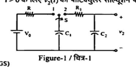
7 MarksaIn the circuit of fig-1 the switch S is moved from position 1 to 2 at $t = 0$, having been in position 1 for a long time before $t = 0$. Capacitor $C_2$ is uncharged at $t = 0$. i) Find the particular solution for $i(t)$ for $t > 0$ ii) Find the particular solution for $v_2(t)$ for $t > 0$
How to answer
- Find initial voltage on C1: v1(0) = V0, v2(0) = 0
- Write KVL for t > 0 with switch at position 2: R1*i(t) + (1/C1) int i dt + (1/C2) int i dt = 0
- Calculate equivalent capacitance Ceq = (C1*C2)/(C1+C2) and time constant tau = R1*Ceq
- Derive expression for i(t)
- Determine v2(t) by integrating i(t)/C2 with initial condition v2(0) = 0
-
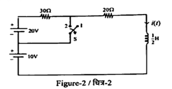
7 MarksbThe circuit of fig. 2 reaches a steady state in position 2 and at $t = 0$ the switch S is moved to position 1. Find $i(t)$.
How to answer
- Find initial inductor current i(0^-) from steady state in position 2
- Find final inductor current i(infinity) in position 1
- Find Thevenin equivalent resistance Rth seen by the inductor for t > 0
- Calculate time constant tau = L / Rth
- Formulate complete response expression i(t) = i(infinity) + [i(0+) - i(infinity)] * exp(-t/tau)
-
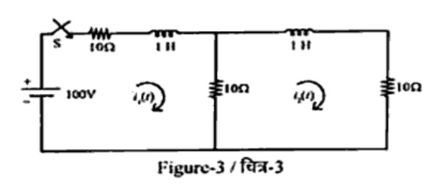
7 MarksaIn the network shown in fig. 3, the switch S is closed at $t = 0$. Find the value of $i_1(t)$ and $i_2(t)$.
How to answer
- State initial conditions: i1(0-) = 0, i2(0-) = 0
- Convert circuit to s-domain with transform of 100V step input (100/s)
- Formulate s-domain mesh equations for loop 1 and loop 2
- Solve for I1(s) and I2(s) using Cramer's rule or substitution
- Take inverse Laplace transform to obtain time-domain solutions i1(t) and i2(t)
-
7 MarksbState and prove RLC series resonance.
How to answer
- Define series resonance: condition where inductive reactance equals capacitive reactance and total impedance is purely resistive
- Write series impedance expression: Z = R + j(omega*L - 1/(omega*C))
- Set imaginary part to zero: omega*L - 1/(omega*C) = 0
- Derive resonant frequency f0 = 1 / (2*pi*sqrt(L*C))
- Sketch impedance and current response curves vs frequency, noting unity power factor and maximum current at resonance
-
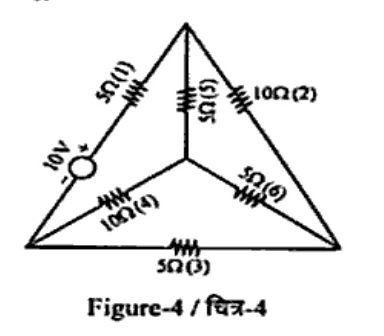
14 MarksFor the network shown in fig-4 write the tie set matrix for the twigs (4, 5, 6) and determine the loop currents and branch currents for the same.
How to answer
- Identify network graph, tree with twigs {4, 5, 6} and co-tree links {1, 2, 3}
- Form fundamental loops corresponding to each link
- Construct fundamental tie-set matrix [B] specifying orientations
- Formulate network equilibrium equations using branch impedance matrix [Zb]: [B][Zb][B]^T [IL] = [B][Vs]
- Solve for loop currents [IL] and determine branch currents [Ib] = [B]^T [IL]
-
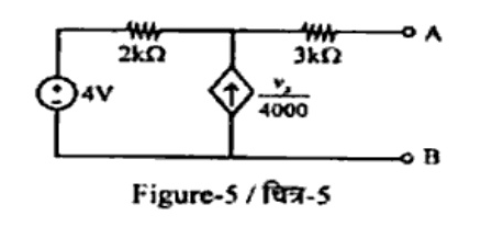
7 MarksaDetermine the value of $R_L$ to be connected across AB in fig. 5, for maximum power transfer. Also calculate the maximum power absorbed by the $R_L$.
How to answer
- Find open-circuit voltage Vth across terminals A-B
- Find short-circuit current Isc or apply a test source to determine Rth with dependent source present
- Set RL = Rth for maximum power transfer condition
- Calculate maximum power using Pmax = Vth^2 / (4 * Rth)
-
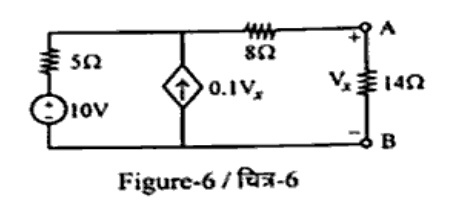
7 MarksbFind the current in the $14\,\Omega$ resistor of the circuit of fig. 6 by Thevenin theorem.
How to answer
- Remove the 14 ohm load resistor across terminals A-B
- Determine the open-circuit voltage Vth across terminals A-B, noting the control variable Vx
- Determine Rth by applying a 1V test source or finding short-circuit current Isc
- Draw the Thevenin equivalent circuit with Vth, Rth, and RL = 14 ohm
- Calculate the load current IL = Vth / (Rth + 14)
-
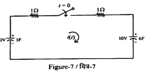
7 MarksaSolve for $i(t)$ in the circuit as shown in fig. 7 in which 3F capacitor is initially charged to 20V and 6F capacitor to 10V, and the switch is closed at $t = 0$. Also draw the S-transformed circuit.
How to answer
- Identify initial condition voltages with proper polarities: V1(0) = 20V, V2(0) = 10V
- Draw s-transformed equivalent circuit showing capacitors as 1/(sC) in series with V(0)/s voltage sources
- Write loop KVL equation in s-domain: I(s) * [1 + 1 + 1/(3s) + 1/(6s)] = (20/s - 10/s)
- Simplify expression for I(s)
- Perform inverse Laplace transform to find i(t) for t > 0
-
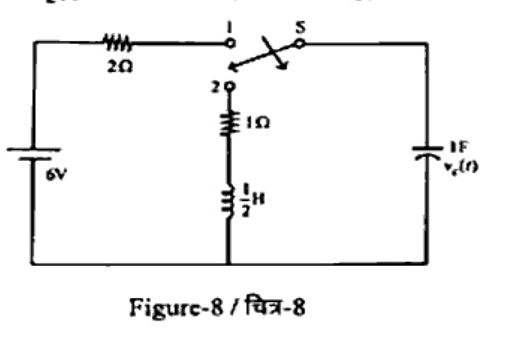
7 MarksbIn the circuit of fig-8, switch is in position 1 for long time and moved to position 2 at $t = 0$. Find the voltage across the capacitor $v_c(t)$ for $t > 0$.
How to answer
- Determine initial conditions at t = 0-: vc(0-) and iL(0-) with switch in position 1
- Write differential equation or s-domain equation for t > 0 with switch in position 2
- Find characteristic roots to identify damping condition (overdamped, critically damped, or underdamped)
- Apply boundary conditions vc(0+) and dv_c(0+)/dt = i_c(0+)/C
- Write the final expression for vc(t) for t > 0
-
7 MarksaState and prove super position theorem.
How to answer
- State superposition theorem formally
- State conditions of applicability (linear and bilateral elements)
- Describe procedure: deactivate independent sources (short voltage sources, open current sources)
- Provide mathematical proof using matrix formulation of network equations ([Z][I] = [V]) or an illustrative two-source network
- Summarize limitations regarding power calculation (non-linear)
-
7 MarksbVerify reciprocity theorem for the circuit shown in fig. 9.
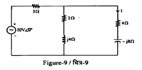
How to answer
- State reciprocity theorem: ratio of response to excitation remains identical upon interchanging excitation and response locations
- Case 1: Calculate current I in the (4 - j8) ohm branch with 10∠0° V source in the input branch
- Case 2: Transfer the 10∠0° V source to the output branch and calculate response current I' in the original source branch
- Compare numerical values of I and I' to show I = I', thus verifying reciprocity
-
14 MarksObtain the Z and Y parameters of the network shown in fig-10.
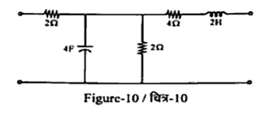
How to answer
- Define Z-parameters: Z11, Z12, Z21, Z22 using open-circuit conditions (I2 = 0 and I1 = 0)
- Calculate Z11 = V1/I1 |(I2=0) and Z21 = V2/I1 |(I2=0)
- Calculate Z22 = V2/I2 |(I1=0) and Z12 = V1/I2 |(I1=0)
- Formulate Z-matrix
- Compute Y-matrix by inverting the Z-matrix ([Y] = [Z]^-1) or directly using short-circuit tests
-
14 MarksWrite short notes on any two of the following: a) Tellegen's theorem b) Hybrid parameters c) Millman theorem
How to answer
- For Tellegen's theorem: state sum of products of branch voltages and currents is zero (sum v_k * i_k = 0); mention independence from element characteristics (linear, nonlinear, time-variant)
- For Hybrid parameters: define h11, h12, h21, h22 equations (V1 = h11*I1 + h12*V2, I2 = h21*I1 + h22*V2), units, and equivalent circuit
- For Millman's theorem: state theorem for finding common voltage of parallel voltage sources with series impedances Vm = sum(Ek*Yk) / sum(Yk), and draw equivalent circuit
Go to where you left off?
Quick Add to Notes
Save questions, your own notes and screenshots into notes filed by unit. It takes a free account.
Create free accountHave an account? Log in
Notes Panel