EC-305 · Network Analysis/Unsolved PYQ Paper
EC-305 Network Analysis - Dec 2023 Question Paper
Under each question, How to answer lists the points an answer should cover, outlined by CampusPrep from the syllabus. Check the details against your textbook.
-
7 MarksaCalculate the current in the $3\Omega$ resistor for the circuit shown -
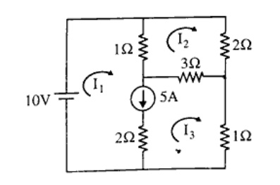
How to answer
- Identify mesh currents $I_1$, $I_2$, and $I_3$ or node voltages.
- Formulate KVL equations including supermesh constraint due to the 5A current source between meshes.
- Solve the system of simultaneous linear equations for the mesh currents.
- Calculate the net current flowing through the $3\Omega$ resistor ($I_2 - I_3$ or appropriate direction).
-
7 MarksbThree impedances of $(70.7 + j70.7)\text{ Ohm}$, $(120 + j160)\text{ Ohm}$ and $(120 + j90)\text{ Ohm}$ are connected in parallel across a $250\text{ V}$ supply. Determine i) Admittance of the circuit ii) Supply current iii) Circuit power factor
How to answer
- Calculate individual admittances: $Y_1 = 1/Z_1$, $Y_2 = 1/Z_2$, $Y_3 = 1/Z_3$.
- Find total admittance: $Y_T = Y_1 + Y_2 + Y_3 = G + jB$.
- Calculate supply current: $I = V \times Y_T$.
- Determine the overall power factor: $\cos \phi = G / |Y_T|$ (lagging).
-
7 MarksaExplain the mesh analysis and nodal analysis with example.
How to answer
- Define Mesh Analysis based on KVL, selection of loop currents, and formulation of loop equations.
- Provide an illustrative circuit example demonstrating Mesh Analysis.
- Define Nodal Analysis based on KCL, selection of reference node, and formulation of node equations.
- Provide an illustrative circuit example demonstrating Nodal Analysis.
-
7 MarksbWhat is resonance? Explain parallel resonance condition in detail with circuit and equations.
How to answer
- Define electrical resonance (unity power factor condition where inductive and capacitive reactances cancel).
- Draw circuit diagram of practical parallel R-L and C circuit.
- Write admittance equation $Y = Y_{RL} + Y_C$ and separate real and imaginary parts.
- Equate imaginary part (susceptance) to zero to derive resonant frequency $\omega_r$.
- Derive expression for dynamic impedance $Z_{dynamic} = L / (CR)$.
-
7 MarksaExplain the following with an example: i) Tree and Co-Tree ii) Twigs and Links iii) Incidence matrix
How to answer
- Define Tree (subgraph containing all nodes without closed loops) and Co-tree (complement of tree).
- Define Twigs (branches of a tree) and Links (branches of co-tree).
- Define Complete and Reduced Incidence Matrix $[A]$ representing node-branch incidence.
- Provide a sample directed graph to illustrate Tree, Co-tree, Twigs, Links, and write its incidence matrix.
-
7 MarksbDraw the graph, one tree and its co-tree for the circuit given below-
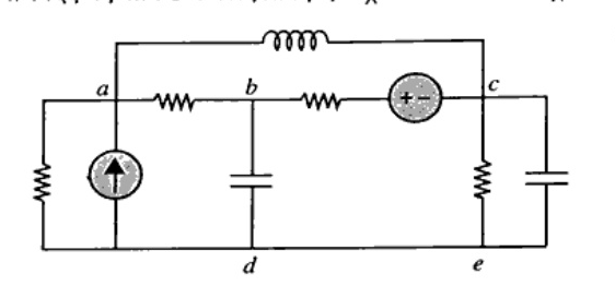
How to answer
- Identify nodes (a, b, c, d, e) and branches from the given circuit.
- Draw the complete directed/undirected network graph replacing all components by line segments.
- Select a valid tree connecting all 5 nodes without forming any closed loop (containing $N-1 = 4$ branches).
- Show the corresponding co-tree containing the remaining link branches.
-
7 MarksaExplain the concept of principle of duality. Also draw the Dual Circuit of Parallel RLC circuit with Current Source.
How to answer
- Explain principle of duality in electrical networks (equations have identical mathematical form under dual variable transformation).
- List dual pairs: current $\leftrightarrow$ voltage, resistance $\leftrightarrow$ conductance, inductance $\leftrightarrow$ capacitance, loop $\leftrightarrow$ node, series $\leftrightarrow$ parallel.
- Draw the parallel RLC circuit with a current source.
- Construct and draw the dual circuit: series RLC circuit driven by an independent voltage source.
-
7 MarksbFind the current through AB in the given circuit using Norton's theorem.
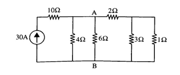
How to answer
- Remove branch AB ($R_L = 6\Omega$) and short-circuit terminals A and B to calculate Norton current $I_N = I_{sc}$.
- Deactivate all independent sources (open current source) and calculate Norton equivalent resistance $R_N$ seen across A-B.
- Draw the Norton equivalent circuit with $I_N$ in parallel with $R_N$ and connected to $R_L = 6\Omega$.
- Compute the load current $I_{AB} = I_N \times \frac{R_N}{R_N + R_L}$.
-
7 MarksaFind $V_{ab}$ using Superposition theorem.
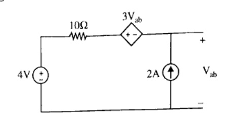
How to answer
- Case 1: Activate 4V source and deactivate 2A current source (open-circuit), keeping the dependent source active; solve for $V_{ab}'$.
- Case 2: Activate 2A current source and deactivate 4V voltage source (short-circuit), keeping the dependent source active; solve for $V_{ab}''$.
- Apply superposition: $V_{ab} = V_{ab}' + V_{ab}''$.
-
7 MarksbGive the statement and prove maximum power transfer theorem with an example.
How to answer
- State the Maximum Power Transfer Theorem for DC circuits.
- Set up the Thevenin equivalent circuit with source $V_{Th}$, internal resistance $R_{Th}$, and load $R_L$.
- Write expression for power $P_L = \left(\frac{V_{Th}}{R_{Th} + R_L}\right)^2 R_L$.
- Differentiate $P_L$ with respect to $R_L$ and equate to zero to prove $R_L = R_{Th}$.
- Derive $P_{max} = \frac{V_{Th}^2}{4 R_{Th}}$ and illustrate with a numerical example.
-
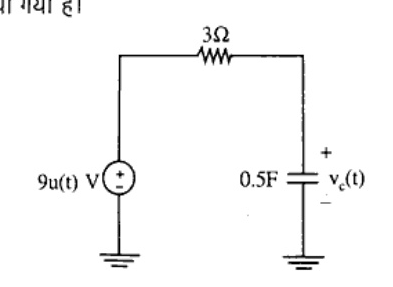
7 MarksaDetermine the voltage $v_c(t)$ shown in figure, given an initial voltage $v_c(0^-) = -2\text{V}$ using Laplace transform method.
How to answer
- Convert the time-domain circuit into s-domain with capacitor modeled as impedance $1/(sC)$ in series with a voltage source $v(0^-)/s$ (or parallel current source).
- Substitute values: $V_{in}(s) = 9/s$, $R = 3\Omega$, $C = 0.5\text{ F}$, $v_c(0^-) = -2\text{ V}$.
- Write node equation for $V_c(s)$ in the s-domain.
- Perform partial fraction expansion of $V_c(s)$.
- Take inverse Laplace transform to obtain $v_c(t)$ for $t \ge 0$.
-
7 MarksbDiscuss about the step response of an RC circuit using Laplace transform.
How to answer
- Draw circuit diagram of series RC circuit excited by a step input $v(t) = V_0 u(t)$.
- Write differential equation: $R \frac{dq}{dt} + \frac{q}{C} = V_0$ or $R C \frac{dv_c}{dt} + v_c = V_0$.
- Take Laplace transform assuming zero initial conditions: $V_c(s) = \frac{V_0}{s(1 + sRC)}$.
- Apply partial fractions: $V_c(s) = V_0 \left(\frac{1}{s} - \frac{1}{s + 1/(RC)}\right)$.
- Take inverse Laplace transform: $v_c(t) = V_0 (1 - e^{-t/RC}) u(t)$ and plot the response curve.
-
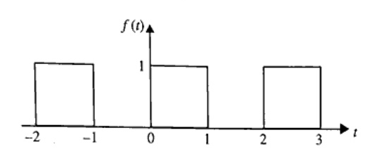
7 MarksaDescribe the Laplace transform of the waveform shown in figure-
How to answer
- Identify the waveform as a periodic square pulse train for $t \ge 0$ with amplitude 1, pulse width 1, and period $T = 2$.
- Express the first cycle $f_1(t)$ using unit step functions: $f_1(t) = u(t) - u(t-1)$.
- Compute the Laplace transform of the first period: $F_1(s) = \frac{1 - e^{-s}}{s}$.
- Use the periodicity property: $F(s) = \frac{F_1(s)}{1 - e^{-sT}} = \frac{1 - e^{-s}}{s(1 - e^{-2s})} = \frac{1}{s(1 + e^{-s})}$.
-
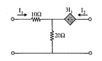
7 MarksbFind the transmission parameters of the following two port network:
How to answer
- Define transmission parameters: $V_1 = A V_2 - B I_2$, $I_1 = C V_2 - D I_2$.
- Apply open-circuit condition at port 2 ($I_2 = 0$) to compute $A = \left.\frac{V_1}{V_2}\right|_{I_2=0}$ and $C = \left.\frac{I_1}{V_2}\right|_{I_2=0}$.
- Apply short-circuit condition at port 2 ($V_2 = 0$) to compute $B = \left.-\frac{V_1}{I_2}\right|_{V_2=0}$ and $D = \left.-\frac{I_1}{I_2}\right|_{V_2=0}$.
- Present the final ABCD parameter matrix.
-
7 MarksaExplain Y-parameters in detail. Also determine its conditions for reciprocity and symmetry.
How to answer
- Define short-circuit admittance (Y) parameters with equations: $I_1 = Y_{11} V_1 + Y_{12} V_2$, $I_2 = Y_{21} V_1 + Y_{22} V_2$.
- Draw equivalent circuit model for Y-parameters.
- Define and derive condition for reciprocity: $Y_{12} = Y_{21}$.
- Define and derive condition for symmetry: $Y_{11} = Y_{22}$.
-
7 MarksbObtain the hybrid parameters in terms of Z-parameters.
How to answer
- Write the standard Z-parameter equations: $V_1 = z_{11} I_1 + z_{12} I_2$ and $V_2 = z_{21} I_1 + z_{22} I_2$.
- Write the standard h-parameter equations: $V_1 = h_{11} I_1 + h_{12} V_2$ and $I_2 = h_{21} I_1 + h_{22} V_2$.
- Rearrange second Z-equation to express $I_2$ in terms of $I_1$ and $V_2$: $I_2 = -\frac{z_{21}}{z_{22}} I_1 + \frac{1}{z_{22}} V_2$.
- Substitute $I_2$ into the first Z-equation to express $V_1$ in terms of $I_1$ and $V_2$.
- Compare coefficients to obtain: $h_{11} = \frac{\Delta Z}{z_{22}}$, $h_{12} = \frac{z_{12}}{z_{22}}$, $h_{21} = -\frac{z_{21}}{z_{22}}$, and $h_{22} = \frac{1}{z_{22}}$.
Go to where you left off?
Quick Add to Notes
Save questions, your own notes and screenshots into notes filed by unit. It takes a free account.
Create free accountHave an account? Log in
Notes Panel