EC-305 · Network Analysis/Unsolved PYQ Paper
EC-305 Network Analysis - Dec 2024 Question Paper
Under each question, How to answer lists the points an answer should cover, outlined by CampusPrep from the syllabus. Check the details against your textbook.
-
7 MarksaFind the voltage across the dependent current source
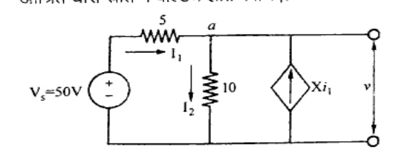
How to answer
- Identify node a and set its voltage as v
- Write KCL equation at node a
- Express controlling current I_1 in terms of nodal voltage v
- Solve for voltage v across the dependent source
-
7 MarksbDiscuss dot Convention used in Magnetically coupled Circuits with suitable example.
How to answer
- Define dot convention rule for magnetically coupled coils
- Explain sign of mutually induced voltage with respect to current entering or leaving the dot
- Draw circuit diagram with two coupled inductors having dot markings
- Provide a suitable mesh equation example
-
7 MarksaAn impedance $Z_1 = 10 + j10\ \Omega$ is connected in parallel with another impedance of resistance $8.5\ \Omega$ and a variable capacitance connected in series. Find $C$ such that the circuit is in resonance at $5\text{ KHz}$
How to answer
- Find admittance of branch 1: $Y_1 = \frac{1}{10+j10} = 0.05 - j0.05\text{ S}$
- Write admittance of branch 2: $Y_2 = \frac{1}{8.5 - jX_C} = \frac{8.5 + jX_C}{(8.5)^2 + X_C^2}$
- Set total imaginary part (susceptance) to zero: $\frac{X_C}{72.25 + X_C^2} - 0.05 = 0$
- Solve quadratic equation for $X_C$
- Calculate $C = \frac{1}{2\pi f X_C}$ for $f = 5000\text{ Hz}$
-
7 MarksbFor the network shown in figure below draw the oriented graph and frame the cut-set matrix
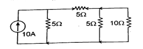
How to answer
- Label all nodes and branches with arbitrary orientation
- Draw the oriented graph representing the circuit topology
- Select a suitable tree of the graph
- Identify fundamental cut-sets associated with each twig/tree branch
- Formulate and write the cut-set matrix (fundamental cut-set matrix)
-
7 MarksaExplain the following with suitable example: i) Sub graph ii) Connected graph iii) Planar graph iv) Tree and Co-Tree
How to answer
- Define Sub graph with an illustrative figure
- Define Connected graph (path between every pair of vertices)
- Define Planar graph (can be drawn on a plane without intersecting edges)
- Define Tree (connected subgraph containing all nodes without closed loops) and Co-Tree (complementary graph consisting of links)
- Provide diagrammatic examples for each
-
7 MarksbDraw the parallel resonant circuit and derive the expression for resonant frequency.
How to answer
- Draw standard parallel resonant circuit (RL branch in parallel with RC or C branch)
- Write total admittance expression $Y(j\omega)$
- Separate real and imaginary components (conductance and susceptance)
- Apply condition for resonance: Susceptance $B = 0$
- Solve for $\omega_0$ and $f_0$
-
7 MarksaState and explain Thevenin's theorem with suitable example.
How to answer
- State Thevenin's theorem statement accurately
- Explain calculation of $V_{th}$ (open-circuit voltage) and $R_{th}$ (equivalent resistance looking into the terminals)
- Draw Thevenin equivalent circuit ($V_{th}$ in series with $R_{th}$ and $R_L$)
- Demonstrate application with a simple circuit example
-
7 MarksbFind the value of $R_L$ for maximum power transfer in the circuit shown below. And find the maximum power.
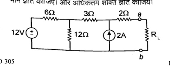
How to answer
- Remove load resistor $R_L$ connected between terminals $a$ and $b$
- Determine Thevenin resistance $R_{th}$ by deactivating independent sources ($12\text{ V} \rightarrow$ short, $2\text{ A} \rightarrow$ open): $R_{th} = 2 + 3 + (6 \parallel 12) = 5 + 4 = 9\ \Omega$
- Hence $R_L = R_{th} = 9\ \Omega$
- Find open-circuit voltage $V_{th}$ across terminals $a-b$ using nodal/mesh analysis
- Calculate maximum power using $P_{max} = \frac{V_{th}^2}{4 R_{th}}$
-
7 MarksaFor the circuit given below, Find the current 'I' and then verify the reciprocity theorem
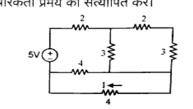
How to answer
- Set up mesh/nodal equations to calculate current $I$ in the $4\ \Omega$ bottom branch
- Interchange the excitation ($5\text{ V}$ source) to the branch where $I$ was measured
- Calculate the new current in the original source branch
- Show that the ratio of excitation to response is equal in both cases, verifying the reciprocity theorem
-
7 MarksbA $200\Omega$ resistor is in series with an inductor L. The initial value of the inductor current is $5\text{ mA}$ and its value after $5\text{ms}$ is $3\text{ mA}$. Find the time constant and the inductance.
How to answer
- Write decay current expression: $i(t) = I_0 e^{-t/\tau}$
- Substitute values: $3 = 5 e^{-5 \times 10^{-3}/\tau} \implies e^{-0.005/\tau} = 0.6$
- Calculate $\tau$: $\tau = -0.005 / \ln(0.6) = 0.009789\text{ s} \approx 9.79\text{ ms}$
- Calculate inductance: $L = R \times \tau = 200 \times 0.009789 \approx 1.958\text{ H}$
-
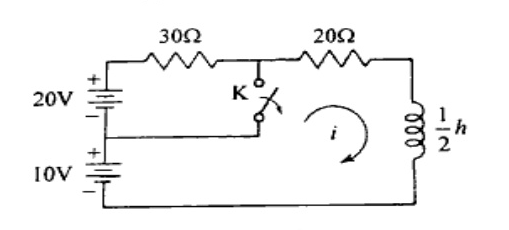
7 MarksaThe network as shown in figure below reaches a steady state with switch K closed. At $t = 0$ switch K is opened. Find the $I(t)$.
How to answer
- Determine initial inductor current $i(0^-) = i(0^+)$ when switch K is closed in steady state
- For $t > 0$, switch K is open; identify the single loop circuit
- Find the final steady-state current $i(\infty)$
- Determine equivalent resistance $R_{eq}$ and time constant $\tau = \frac{L}{R_{eq}}$
- Write full transient equation $i(t) = i(\infty) + [i(0^+) - i(\infty)] e^{-t/\tau}$
-
7 MarksbState and explain Initial Value and Final value theorem
How to answer
- State Initial Value Theorem: $\lim_{t \to 0} f(t) = \lim_{s \to \infty} s F(s)$
- State conditions for IVT validity
- State Final Value Theorem: $\lim_{t \to \infty} f(t) = \lim_{s \to 0} s F(s)$
- State conditions for FVT validity (poles of $s F(s)$ must lie in the left half of the s-plane)
- Provide a simple illustrative example
-
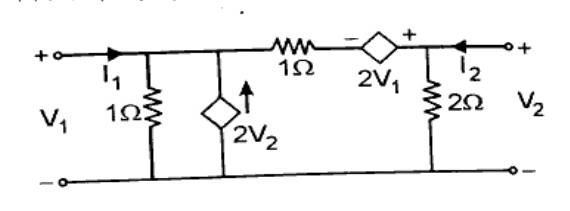
7 MarksaDetermine the 'h' parameters of the network shown in figure
How to answer
- Define h-parameter equations: $V_1 = h_{11} I_1 + h_{12} V_2$ and $I_2 = h_{21} I_1 + h_{22} V_2$
- Short-circuit port 2 ($V_2 = 0$) to find $h_{11} = \frac{V_1}{I_1}\Big|_{V_2=0}$ and $h_{21} = \frac{I_2}{I_1}\Big|_{V_2=0}$
- Open-circuit port 1 ($I_1 = 0$) to find $h_{12} = \frac{V_1}{V_2}\Big|_{I_1=0}$ and $h_{22} = \frac{I_2}{V_2}\Big|_{I_1=0}$
- Formulate and state the resulting h-parameter matrix
-
7 MarksbDefine Z and Y parameters of a Two port network and determine the relationship between the above parameters.
How to answer
- Define Z-parameters: $[V] = [Z][I]$ with individual parameter definitions
- Define Y-parameters: $[I] = [Y][V]$ with individual parameter definitions
- Express relationship in matrix form: $[Y] = [Z]^{-1}$
- Determine inverse matrix of $[Z]$ using determinant $\Delta Z = Z_{11}Z_{22} - Z_{12}Z_{21}$
- Equate corresponding elements: $Y_{11} = \frac{Z_{22}}{\Delta Z}$, $Y_{12} = -\frac{Z_{12}}{\Delta Z}$, $Y_{21} = -\frac{Z_{21}}{\Delta Z}$, $Y_{22} = \frac{Z_{11}}{\Delta Z}$
-
14 MarksWrite a short notes on any two: i) Image Parameter ii) Steady State Analysis iii) Controlled and un controlled sources iv) Dual Networks
How to answer
- Image Parameters: definition of image impedances $Z_{i1}, Z_{i2}$ and propagation constant $\theta$
- Steady State Analysis: AC/DC sinusoidal steady-state, phasor domain representations, and impedance techniques
- Controlled and uncontrolled sources: definitions, VCVS, VCCS, CCVS, CCCS vs independent voltage/current sources with symbols
- Dual Networks: concept of duality, dual pairs (voltage-current, resistance-conductance, inductance-capacitance, loop-node)
Go to where you left off?
Quick Add to Notes
Save questions, your own notes and screenshots into notes filed by unit. It takes a free account.
Create free accountHave an account? Log in
Notes Panel