CE-503 (A) · Structural analysis-II/Unsolved PYQ Paper
CE-503-A Structural Analysis - II - Dec 2024 Question Paper
Under each question, How to answer lists the points an answer should cover, outlined by CampusPrep from the syllabus. Check the details against your textbook.
-
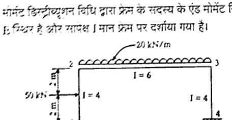
14 MarksDetermine the end moments of the member of the frame by moment distribution method. E is constant and relative I value are indicated on the frame.
How to answer
- Compute fixed-end moments for beam 2-3 under 20 kN/m UDL and for columns with lateral load.
- Compute stiffness factors and distribution factors at joints 2 and 3 using relative I values.
- Perform moment distribution cycles including sway correction for 50 kN lateral load.
- Obtain final end moments for members 1-2, 2-3, 3-4 and equilibrium check.
-
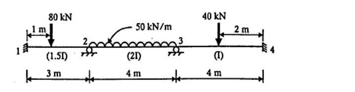
14 MarksDetermine the support moment for the continuous beam. Relative I value are indicated along the member in each span. E is constant. Use Kani's method.
How to answer
- Calculate fixed-end moments for spans 1-2 with 80 kN, 2-3 with 50 kN/m UDL, 3-4 with 40 kN.
- Calculate rotation factors at joints 2 and 3 using relative I/L with E constant.
- Perform Kani's iteration for rotation contributions and displacement if any.
- Compute final support moments from fixed-end plus rotation contributions.
-
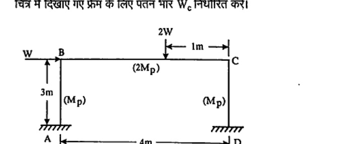
14 MarksDetermine the collapse load $W_c$ for the frame shown in Fig.
How to answer
- Identify possible collapse mechanisms: beam, sidesway and combined.
- Compute virtual work equations with plastic moments Mp for columns and 2Mp for beam.
- Solve for W in each mechanism from external work = internal plastic work.
- Select minimum W as collapse load Wc.
-
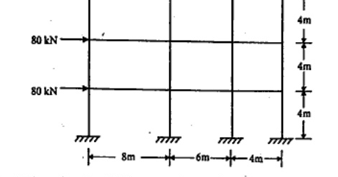
14 MarksAnalysis the frame by portal method as shown in Fig.
How to answer
- Assume inflection points at mid-height of columns and mid-span of beams per portal method.
- Distribute storey shear to interior and exterior columns.
- Compute column shears and moments then beam moments by joint equilibrium.
- Summarize axial, shear and moments for frame.
-
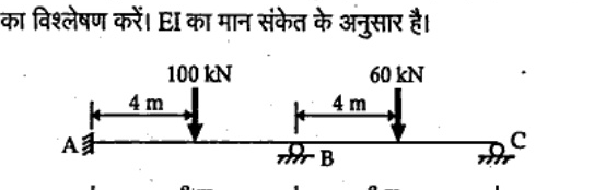
14 MarksUsing the flexibility matrix method, analyse the continuous beam shown in Fig. The value of EI is as indicated.
How to answer
- Select redundants and release structure for flexibility method.
- Compute flexibility coefficients by unit load and displacements by loads.
- Solve compatibility equation for redundant reactions.
- Draw shear force and bending moment diagrams.
-
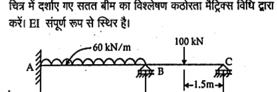
14 MarksAnalyse the continuous beam shown in Fig. By stiffness matrix method. EI is constant throughout.
How to answer
- Discretize joints and degrees of freedom with EI constant.
- Form element stiffness matrices for spans AB and BC.
- Assemble global stiffness matrix and load vector for 60 kN/m UDL and 100 kN.
- Solve for displacements and member end forces.
-
14 MarksCompute the ordinate of influence line for moment at mid span of BC for the beam showing in figure at 1 m interval and draw influence line diagram. Assume moment of inertia to be constant throughout.

How to answer
- Use Muller-Breslau or consistent deformation to get ILD expression for moment at D.
- Compute ordinates at 1 m intervals along 8 m beam A-B-C.
- Tabulate ordinates at points 1-6 and supports.
- Plot influence line diagram for moment at midspan of BC.
-
14 MarksCompute the ordinate of influence line for reaction $R_A$ for the beam showing in figure at 1 m interval and draw influence line diagram. Assume moment of inertia to be constant throughout.

How to answer
- Apply Muller-Breslau for reaction RA by releasing vertical restraint at A.
- Compute ILD ordinates at 1 m intervals over 11 m beam.
- Tabulate values at A, B, C and intermediate points.
- Draw influence line diagram for RA.
Go to where you left off?
Quick Add to Notes
Save questions, your own notes and screenshots into notes filed by unit. It takes a free account.
Create free accountHave an account? Log in
Notes Panel