BT-104 · Basic Electrical & Electronics Engineering/Unsolved PYQ Paper
BT-104 Basic Electrical and Electronics Engineering - Dec 2023 Question Paper
Under each question, How to answer lists the points an answer should cover, outlined by CampusPrep from the syllabus. Check the details against your textbook.
-
7 MarksaUse mesh analysis to determine the three mesh current in the circuit of the figure below.
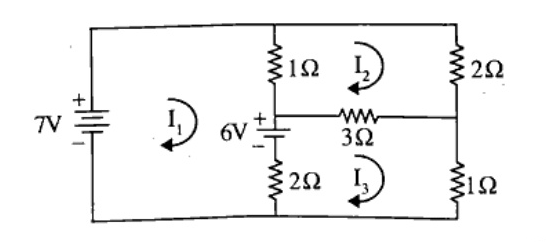
How to answer
- Formulate KVL equations for mesh 1, mesh 2, and mesh 3
- Express in matrix form $[R][I] = [V]$
- Solve the simultaneous equations using Cramer's rule or substitution
- State values of $I_1$, $I_2$, and $I_3$ with appropriate units
-
7 MarksbUsing super position, find the $V_0$ in the circuit shown in figure below.
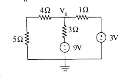
How to answer
- State the Superposition Theorem
- Case 1: Retain 9V source, deactivate (short-circuit) 3V source; compute $V_0'$
- Case 2: Retain 3V source, deactivate (short-circuit) 9V source; compute $V_0''$
- Combine algebraic contributions: $V_0 = V_0' + V_0''$
-
7 MarksaDiscuss about the Star Delta transformation using suitable example.
How to answer
- Define Star (Y) and Delta ($\Delta$) configurations with neat schematics
- Write the conversion formulas from Delta to Star: $R_1 = \frac{R_b R_c}{R_a + R_b + R_c}$
- Write the conversion formulas from Star to Delta: $R_a = R_1 + R_2 + \frac{R_1 R_2}{R_3}$
- Provide a numerical or circuit reduction example illustrating the application
-
7 MarksbExplain the following terms pertaining to an A.C. wave: i) Time period ii) RMS value iii) Average value iv) Form factor
How to answer
- Define Time period ($T$) as the time taken to complete one full cycle
- Define RMS (Root Mean Square) value with mathematical integral formula and physical significance (heating effect)
- Define Average value with integral formula over half cycle (for symmetrical AC)
- Define Form factor as ratio of RMS value to Average value ($k_f = 1.11$ for sine wave)
-
7 MarksaA choke coil has resistance of $10\text{ ohm}$ and inductance of $0.05\text{H}$ is connected in series with an condenser of $100\ \mu\text{F}$. The whole circuit has been connected to $200\text{ V}$, $50\text{ Hz}$ supply. Calculate i) Impedance ii) Current iii) Power Factor iv) Real Power
How to answer
- Compute $X_L = 2\pi f L = 2\pi(50)(0.05) \approx 15.71\ \Omega$
- Compute $X_C = \frac{1}{2\pi f C} = \frac{1}{2\pi(50)(100\times 10^{-6})} \approx 31.83\ \Omega$
- Calculate net impedance: $Z = \sqrt{R^2 + (X_L - X_C)^2}$
- Calculate circuit current: $I = V / Z$
- Calculate power factor: $\cos\phi = R / Z$ (leading)
- Calculate real power: $P = V I \cos\phi = I^2 R$
-
7 MarksbDerive an expression of impedance, current, power factor, power in watts in RLC series circuit.
How to answer
- Draw circuit diagram of series RLC connected to AC source $v = V_m \sin(\omega t)$
- Draw phasor diagram showing $V_R, V_L, V_C$ and resultant voltage $V$
- Derive $V = \sqrt{V_R^2 + (V_L - V_C)^2} = I\sqrt{R^2 + (X_L - X_C)^2}$ to find $Z$
- Formulate expression for current $I = V/Z$ and phase angle $\phi = \tan^{-1}\left(\frac{X_L - X_C}{R}\right)$
- Derive power factor $\cos\phi = R/Z$ and real power $P = VI\cos\phi$
-
7 MarksaDiscuss about active, reactive and apparent power in series RLC circuits.
How to answer
- Define Active/Real power ($P = VI\cos\phi$) in watts (W)
- Define Reactive power ($Q = VI\sin\phi$) in volt-amperes reactive (VAR)
- Define Apparent power ($S = VI$) in volt-amperes (VA)
- Draw the power triangle showing $S^2 = P^2 + Q^2$
-
7 MarksbDiscuss about magnetization characteristics of ferromagnetic material.
How to answer
- Explain domain theory of ferromagnetic materials
- Draw and explain the B-H curve (initial magnetization)
- Explain the Hysteresis loop (saturation, retentivity/remanence, coercive force)
- Discuss hysteresis loss and practical importance in machine core selection
-
7 MarksaDiscuss the laws of Electromagnetic induction.
How to answer
- State Faraday's First Law of electromagnetic induction
- State Faraday's Second Law with formula $e = -N \frac{d\Phi}{dt}$
- State Lenz's Law and explain the physical significance of the negative sign (conservation of energy)
-
7 MarksbOpen circuit and short circuit test on a single phase transformer gave the following results. $V_0 = 200\text{V}$, $I_0 = 0.7\text{A}$, $W_0 = 20\text{ Watt}$ Test from primary side $V_s = 10\text{V}$, $I_s = 10\text{A}$, $W_s = 40\text{ Watt}$ test from secondary side. Determine the equivalent circuit parameters referred to primary side.
How to answer
- From OC Test: calculate $\cos\phi_0 = \frac{W_0}{V_0 I_0}$, core loss current $I_c = I_0\cos\phi_0$, magnetizing current $I_m = I_0\sin\phi_0$
- Determine shunt parameters: $R_0 = \frac{V_0}{I_c}$ and $X_0 = \frac{V_0}{I_m}$
- From SC Test: calculate $R_{02} = \frac{W_s}{I_s^2}$, $Z_{02} = \frac{V_s}{I_s}$, and $X_{02} = \sqrt{Z_{02}^2 - R_{02}^2}$
- Identify turn ratio $K$ or refer parameters directly to primary side $R_{01}$ and $X_{01}$
- Draw the equivalent circuit referred to primary with calculated values
-
7 MarksaDraw and explain the complete Torque-slip characteristics of 3 phase induction motor.
How to answer
- Draw the complete torque-slip curve across three regions: motoring ($0 < s < 1$), generating ($s < 0$), and braking/plugging ($s > 1$)
- State the torque equation: $T \propto \frac{s E_2^2 R_2}{R_2^2 + (s X_2)^2}$
- Explain low-slip region (linear relationship, $T \propto s$)
- Explain high-slip region (inversely proportional, $T \propto 1/s$)
- Highlight starting torque, pull-out/maximum torque, and slip at maximum torque
-
7 MarksbThe core loss in a 3 phase induction motor is $100\text{W}$ and equals the mechanical loss, stator copper loss is $150\text{W}$. When developing $2000\text{W}$ as the shaft power. What is the efficiency of the machine. Assume the slip as $4\%$.
How to answer
- Calculate gross mechanical power developed: $P_{mech} = P_{out} + \text{mechanical loss} = 2000 + 100 = 2100\text{ W}$
- Find rotor power input: $P_g = \frac{P_{mech}}{1 - s} = \frac{2100}{1 - 0.04} = \frac{2100}{0.96} = 2187.5\text{ W}$
- Calculate total motor input power: $P_{in} = P_g + P_{scu} + P_{core} = 2187.5 + 150 + 100 = 2437.5\text{ W}$
- Calculate efficiency: $\eta = \frac{P_{out}}{P_{in}} \times 100 = \frac{2000}{2437.5} \times 100 \approx 82.05\%$
-
7 MarksaWhat do you understand by Adder circuit? Draw and explain the working principle of full adder circuit.
How to answer
- Define adder circuit (combinational digital circuit for binary addition)
- Describe Full Adder (adds three 1-bit binary inputs: $A$, $B$, and $C_{in}$)
- Provide Truth Table for Full Adder showing inputs $A, B, C_{in}$ and outputs $Sum, C_{out}$
- Write Boolean equations: $Sum = A \oplus B \oplus C_{in}$, $C_{out} = AB + C_{in}(A \oplus B)$
- Draw logic circuit diagram using basic gates or two half adders and an OR gate
-
7 MarksbIn a fixed bias circuit using n-p-n transistor, find the operating point if $V_{CC} = 24\text{V}$, $R_B = 220\text{k}$, $R_C = 4.7\text{k}$.
How to answer
- Assume silicon transistor ($V_{BE} = 0.7\text{V}$) and typical value of $\beta$ (e.g., $\beta = 100$, or state in terms of $\beta$)
- Calculate base current: $I_B = \frac{V_{CC} - V_{BE}}{R_B} = \frac{24 - 0.7}{220\times 10^3} \approx 105.9\ \mu\text{A}$
- Calculate collector current: $I_C = \beta I_B$
- Calculate collector-emitter voltage: $V_{CE} = V_{CC} - I_C R_C$
- State the operating point $Q(V_{CE}, I_C)$
-
14 MarksWrite a short note on any Two. i) J-K Flip Flop ii) Dependent and Independent Sources iii) Open circuit and short circuit test iv) De-Morgan's Theorem
How to answer
- For J-K Flip Flop: Explain logic symbol, truth table, race-around condition, and toggle operation
- For Dependent and Independent Sources: Define independent voltage/current sources and four types of dependent sources (VCVS, VCCS, CCVS, CCCS)
- For Open circuit and short circuit test: Explain purpose of OC test (core loss, $R_0, X_0$) and SC test (copper loss, $R_{01}, X_{01}$) of a transformer
- For De-Morgan's Theorem: State both theorems $(\overline{A+B} = \bar{A}\cdot\bar{B}$ and $\overline{A\cdot B} = \bar{A}+\bar{B})$ with truth tables
Go to where you left off?
Quick Add to Notes
Save questions, your own notes and screenshots into notes filed by unit. It takes a free account.
Create free accountHave an account? Log in
Notes Panel