BT-104 · Basic Electrical & Electronics Engineering/Unsolved PYQ Paper
BT-104 Basic Electrical and Electronics Engineering - Jun 2023 Question Paper
Under each question, How to answer lists the points an answer should cover, outlined by CampusPrep from the syllabus. Check the details against your textbook.
-
7 MarksaUsing the mesh analysis, find the $I_0$ in the circuit as given below.
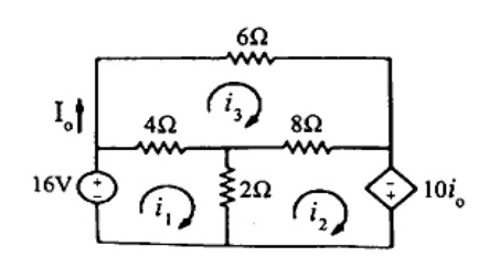
How to answer
- Identify mesh currents $i_1$, $i_2$, and $i_3$
- Express dependent variable $i_0$ (or $I_0$) in terms of mesh currents
- Formulate KVL equations for mesh 1, mesh 3, and the supermesh involving mesh 2
- Solve the simultaneous equations to find $I_0$
-
7 MarksbIn the figure below, find the current flowing through $R_1$ using Thevenin's Theorem.
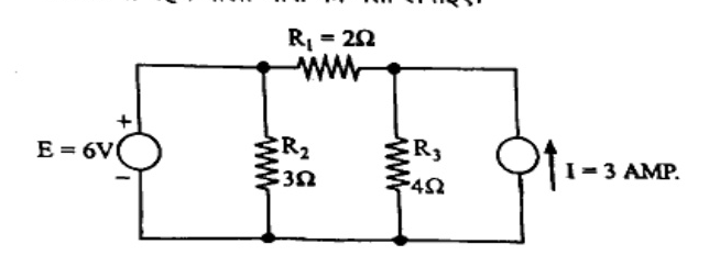
How to answer
- Remove load resistor $R_1 = 2\,\Omega$ to determine terminals
- Calculate Thevenin voltage $V_{th}$ across open terminals
- Deactivate independent sources (short voltage source, open current source) to compute $R_{th}$
- Draw Thevenin equivalent circuit with $R_1$ connected and calculate $I_{R_1} = V_{th} / (R_{th} + R_1)$
-
7 MarksaWhat do you understand by Source. Discuss about different types of Dependent and Independent Voltage and current Sources with suitable sketch.
How to answer
- Define an electrical source (active element supplying energy)
- Differentiate independent (ideal vs practical voltage and current) sources
- Explain the four types of dependent sources: VCVS, CCVS, VCCS, CCCS
- Sketch standard symbols for independent and controlled sources
-
7 MarksbDefine the following: i) Alternating Quantity ii) R.M.S. Value iii) Average value iv) Form factor. v) Peak factor
How to answer
- Define alternating quantity as a time-varying waveform that alternates polarity
- Define RMS value with formula $I_{rms} = \sqrt{\frac{1}{T}\int_0^T i^2(t) dt}$
- Define Average value over a half cycle with formula $I_{avg} = \frac{1}{T/2}\int_0^{T/2} i(t) dt$
- Define Form Factor as $\text{RMS value} / \text{Average value}$ ($1.11$ for sine wave)
- Define Peak Factor as $\text{Peak value} / \text{RMS value}$ ($1.414$ for sine wave)
-
7 MarksaA coil having a resistance of $10\text{ ohms}$ and an inductance of $0.2\text{H}$ is connected in series with a $100 \times 10^{-6}\text{ F}$ capacitor across a $230\text{V}, 50\text{Hz}$ supply, Calculate: i) The active and reactive components of the current ii) The voltage across the coil, Draw the phasor diagram.
How to answer
- Calculate reactances: $X_L = 2\pi(50)(0.2) = 62.83\,\Omega$, $X_C = 1/(2\pi(50)(100\times 10^{-6})) = 31.83\,\Omega$
- Determine total impedance $Z = R + j(X_L - X_C) = 10 + j31\,\Omega$, and magnitude $|Z| = 32.57\,\Omega$, $\phi = 72.13^\circ$
- Find current $I = 230 / 32.57 = 7.06\text{ A}$; active component $I\cos\phi$, reactive component $I\sin\phi$
- Calculate coil voltage $V_{coil} = I Z_{coil} = I \sqrt{R^2 + X_L^2}$
- Draw complete phasor diagram showing supply voltage, current, component drops, and coil voltage
-
7 MarksbA balanced star connected load of $8 + 6j\text{ ohm}$ is connected across three phase, $50\text{Hz}, 440\text{V}$ supply system. Calculate i) Line current ii) Power absorbed iii) Reactive volt ampere
How to answer
- Calculate phase voltage $V_{ph} = 440 / \sqrt{3} \approx 254.03\text{ V}$
- Calculate impedance magnitude $|Z_{ph}| = \sqrt{8^2 + 6^2} = 10\,\Omega$ and $\cos\phi = 8/10 = 0.8$, $\sin\phi = 0.6$
- Compute line current $I_L = I_{ph} = 254.03 / 10 = 25.4\text{ A}$
- Compute power absorbed $P = 3 I_{ph}^2 R = \sqrt{3} V_L I_L \cos\phi$
- Compute reactive volt-amperes $Q = \sqrt{3} V_L I_L \sin\phi$
-
7 MarksaState the different types of transformers. Describe the construction and general principle of transformer.
How to answer
- Classify transformers based on voltage level, construction, phases, application
- Explain construction: magnetic core (silicon steel laminations) and windings (primary and secondary)
- State working principle based on Faraday's law of electromagnetic induction and mutual induction
- Provide a schematic diagram of a single-phase transformer
-
7 MarksbWhat do you understand by Self inductance and mutual inductance? Derive the relation between Self inductance and Mutual Inductance.
How to answer
- Define self-inductance ($L$) as the property opposing change in self-current
- Define mutual inductance ($M$) as the property where current change in one coil induces emf in an adjacent coil
- Write expressions: $L_1 = N_1^2 / S$, $L_2 = N_2^2 / S$, and $M = k N_1 N_2 / S$
- Derive $M = k \sqrt{L_1 L_2}$ where $k$ is the coefficient of coupling
-
7 MarksaOpen circuit and short circuit test on a single phase transformer gave the following results $V_0 = 200\text{V}, I_0 = 0.7\text{A}, W_0 = 20\text{ Watt}$ Test from primary side, $V_s = 10\text{V}, I_s = 10\text{A}, W_s = 40\text{ Watt}$ test from secondary side. Determine the equivalent circuit parameters referred to primary side.
How to answer
- From OC test on primary: compute core loss parameters $R_0$ and $X_0$
- Calculate $\cos\phi_0 = 20 / (200 \times 0.7) = 0.143$, then $I_w$ and $I_m$, giving $R_0$ and $X_0$
- From SC test on secondary: calculate $Z_{02} = 10 / 10 = 1\,\Omega$, $R_{02} = 40 / 10^2 = 0.4\,\Omega$, $X_{02} = \sqrt{1^2 - 0.4^2} = 0.9165\,\Omega$
- Identify transformation ratio $K$ or refer secondary impedance values to primary side ($R_{01}, X_{01}$)
- Draw equivalent circuit with values labelled
-
7 MarksbExplain the construction and working principle of three phase induction motor with suitable diagram.
How to answer
- Explain stator construction (laminated core, 3-phase distributed winding)
- Explain rotor construction (squirrel cage and wound/slip-ring rotor types)
- Describe working principle: generation of rotating magnetic field ($N_s = 120f/P$)
- Explain induced emf, rotor currents, and resultant torque production per Lenz's law
- Provide sketches of motor construction / rotating field phasor
-
7 MarksaA three phase, 6 pole, 50 Hz induction motor has a slip of 1% at no load and 3% at full load, Find i) Synchronous Speed ii) No Load Speed iii) Full Load Speed iv) Frequency of rotor current at full load.
How to answer
- Calculate synchronous speed: $N_s = \frac{120 \times 50}{6} = 1000\text{ rpm}$
- Calculate no-load speed: $N_0 = N_s(1 - s_0) = 1000(1 - 0.01) = 990\text{ rpm}$
- Calculate full-load speed: $N_{fl} = N_s(1 - s_{fl}) = 1000(1 - 0.03) = 970\text{ rpm}$
- Calculate rotor current frequency at full load: $f_r = s_{fl} \times f = 0.03 \times 50 = 1.5\text{ Hz}$
-
7 MarksbDiscuss about types of losses occurring in electrical machine.
How to answer
- Classify machine losses: Copper ($I^2R$) losses in stator/rotor windings
- Core/Iron losses: Hysteresis loss ($P_h = k_h B_{max}^{1.6} f v$) and Eddy current loss ($P_e = k_e B_{max}^2 f^2 t^2 v$)
- Mechanical losses: Friction and windage losses
- Stray load losses and brush contact losses
-
7 MarksaDraw and explain the V-I characteristics of a PN junction.
How to answer
- Explain forward bias operation, cut-in/knee voltage ($0.7\text{V}$ for Si, $0.3\text{V}$ for Ge)
- Explain reverse bias operation, reverse saturation current, and breakdown (Zener/avalanche)
- Draw characteristic curve with forward quadrant and reverse quadrant correctly labeled with units
-
7 MarksbDraw the circuit and explain the characteristics of CB configuration.
How to answer
- Draw circuit diagram of NPN/PNP transistor in common base configuration with biasing sources and meters
- Describe input characteristics ($V_{EB}$ vs $I_E$ at constant $V_{CB}$)
- Describe output characteristics ($I_C$ vs $V_{CB}$ at constant $I_E$) showing active, cutoff, and saturation regions
- Define common base current amplification factor $\alpha = \Delta I_C / \Delta I_E$
-
14 MarksWrite a short note on any two : i) RS Flip Flop ii) Star Delta Transformation iii) De Morgan's Theorem iv) Torque-Slip Characteristics
How to answer
- For (i) RS Flip Flop: logic diagram with NAND/NOR gates, truth table, race-around/undefined state
- For (ii) Star-Delta Transformation: conversion formulas from $Y$ to $\Delta$ and $\Delta$ to $Y$ with circuit diagram
- For (iii) De Morgan's Theorem: state $\overline{A+B} = \bar{A}\cdot\bar{B}$ and $\overline{A\cdot B} = \bar{A}+\bar{B}$, truth table verification
- For (iv) Torque-Slip Characteristics: plot curve showing motor, generator, and braking regions; identify starting torque, pull-out torque, operating region
Go to where you left off?
Quick Add to Notes
Save questions, your own notes and screenshots into notes filed by unit. It takes a free account.
Create free accountHave an account? Log in
Notes Panel