BT-104 · Basic Electrical & Electronics Engineering/Unsolved PYQ Paper
BT-104 Basic Electrical and Electronics Engineering - Nov 2022 Question Paper
Under each question, How to answer lists the points an answer should cover, outlined by CampusPrep from the syllabus. Check the details against your textbook.
-
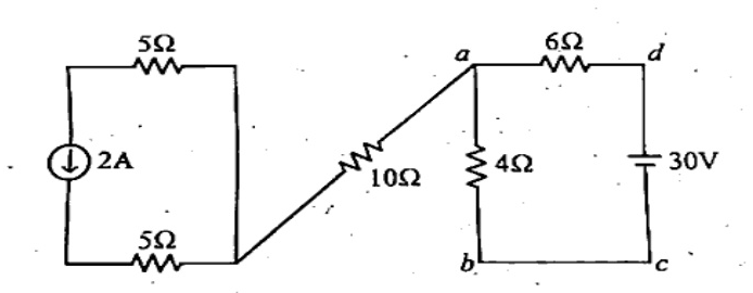
7 MarksaFind the voltage $V_{ab}$ in the network shown below.
How to answer
- Identify independent loops/branches in the circuit
- Calculate current through the loop with the 30V source and resistors (4 ohm and 6 ohm)
- Determine the current through the 10 ohm resistor branch (open/connected to the 2A loop)
- Apply KVL along the path between node a and node b to determine V_ab
-
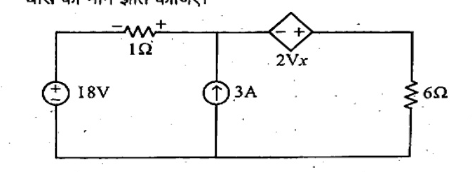
7 MarksbFind the current through $6\Omega$ resistor using Thevenin's theorem.
How to answer
- Remove the 6 ohm load resistor and find open-circuit voltage V_th across load terminals
- Express controlling voltage V_x in terms of circuit parameters to evaluate V_th
- Find short-circuit current I_sc or apply a test source to determine R_th with dependent voltage source 2V_x
- Construct Thevenin equivalent circuit and calculate load current I_L = V_th / (R_th + 6)
-
7 MarksaDraw Phasor diagrams of the following circuits. i) Series R-L-C when $X_L > X_C$ ii) Series R-L-C when $X_L < X_C$ iii) Series R-L-C when $X_L = X_C$
How to answer
- Draw reference current phasor I along horizontal axis
- For i) X_L > X_C: Show V_L leading by 90 deg, V_C lagging by 90 deg, resultant (V_L - V_C) leading, net voltage V leads current I (lagging power factor)
- For ii) X_L < X_C: Net voltage (V_C - V_L) lagging, net voltage lags current (leading power factor)
- For iii) X_L = X_C: V_L cancels V_C, net voltage V = V_R in phase with current (unity power factor / resonance)
-
7 MarksbA 3-$\phi$ balanced system supplies 110V to a delta connected load whose phase impedance is equal to $(3.54 + j3.54)\Omega$. Determine the line currents and draw the Phasor diagram.
How to answer
- State relation for delta connection: V_ph = V_L = 110 V
- Compute impedance magnitude |Z_ph| = sqrt(3.54^2 + 3.54^2) = 5 ohm and phase angle = 45 degrees
- Calculate phase current I_ph = 110 / 5 = 22 A
- Calculate line current I_L = sqrt(3) * I_ph = sqrt(3) * 22 = 38.1 A
- Draw complete phasor diagram showing line/phase voltages and phase/line currents
-
7 MarksaDraw Phasor diagram of a 3-phase delta connected load and find the relation between phase and line voltages and currents.
How to answer
- Schematic diagram of balanced 3-phase delta load
- Establish that line voltage equals phase voltage: V_L = V_ph
- Apply KCL at nodes: I_R = I_RY - I_BR, etc.
- Derive I_L = 2 * I_ph * cos(30) = sqrt(3) * I_ph
- Sketch the corresponding phasor diagram showing currents and voltages
-
7 MarksbA 220 V, 100 Hz, A.C. source supplies a series RLC circuit with a capacitor and a coil. If the coil has 50 mH inductance, find at a resonance frequency of 100 Hz, what is the value of capacitor?
How to answer
- State resonance condition: X_L = X_C or f_r = 1 / (2*pi*sqrt(L*C))
- Rearrange formula for C: C = 1 / (4 * pi^2 * f_r^2 * L)
- Substitute values: f_r = 100 Hz, L = 50 * 10^-3 H
- Calculate C = 1 / (4 * pi^2 * 10000 * 0.05) \approx 50.66 \mu F
-
7 MarksaDraw the typical normal magnetization curve of ferromagnetic material.
How to answer
- Draw B-H magnetization curve with magnetic flux density B on y-axis and magnetic field intensity H on x-axis
- Mark the initial region of low slope (domain rotation/wall movement)
- Mark the linear/steep region (domain alignment)
- Mark the knee point and the saturation region
- Briefly describe each region of the magnetization curve
-
7 MarksbExplain in detail the Applications of DC Machines.
How to answer
- Applications of DC Shunt Motors: lathes, centrifugal pumps, fans, conveyors (constant speed applications)
- Applications of DC Series Motors: electric traction, cranes, hoists, elevators (high starting torque applications)
- Applications of DC Compound Motors: rolling mills, heavy presses, elevators
- Applications of DC Generators: battery charging, electroplating, exciter for alternators
-
7 MarksaDraw and explain the output characteristic of a NPN transistor operation in CE configuration.
How to answer
- Circuit schematic for testing CE output characteristics
- Plot of collector current $I_C$ vs collector-emitter voltage $V_{CE}$ for constant values of base current $I_B$
- Explain active region (linear amplification, collector junction reverse biased, emitter junction forward biased)
- Explain saturation region ($V_{CE} < V_{CE(sat)}$, both junctions forward biased)
- Explain cutoff region ($I_B = 0$, both junctions reverse biased)
-
7 MarksbThe no-load ratio required in a single-phase 50 Hz transformer is 6600/600 V. If the maximum value of flux in the core is to be about 0.08 Wb, find the number of turns in each winding.
How to answer
- State transformer EMF equation: E = 4.44 * f * Phi_m * N
- Calculate primary turns: N_1 = 6600 / (4.44 * 50 * 0.08) = 6600 / 17.76 \approx 371.6 \approx 372 turns
- Calculate secondary turns: N_2 = 600 / (4.44 * 50 * 0.08) = 600 / 17.76 \approx 33.78 \approx 34 turns
- Alternatively, N_2 = N_1 * (E_2 / E_1)
-
7 MarksaEnumerate the various losses in a transformer. How these losses can be minimized?
How to answer
- Iron/Core losses: Hysteresis loss (minimized by using high silicon steel) and Eddy current loss (minimized by using thin laminations)
- Copper/Winding losses ($I^2R$): minimized by using thicker conductors/low resistance copper wire
- Stray losses: minimized by proper magnetic shielding
- Dielectric losses in transformer oil and solid insulation
-
7 MarksbExplain the construction and working principle of three-phase induction motor with suitable diagram.
How to answer
- Construction: Stator (core, 3-phase winding) and Rotor (squirrel cage or slip ring / phase wound)
- Production of Rotating Magnetic Field (RMF) of constant magnitude 1.5 Phi_m rotating at synchronous speed N_s
- Working principle: RMF cuts stationary rotor conductors, inducing EMF and currents
- Lenz's Law and torque production causing rotor to rotate in the direction of RMF to oppose the relative motion
- Neat labeled diagram of stator and rotor construction
-
7 MarksaWhat is the difference between a separately excited and a self-excited generator?
How to answer
- Field excitation source: Separately excited uses independent external DC source; self-excited uses current generated by its own armature
- Residual magnetism: Essential for self-excited generator to build up voltage; not mandatory for separately excited
- Types: Self-excited subdivided into shunt, series, and compound generators
- Control and stability: Separately excited offers stable output over wide range of voltage; self-excited depends on terminal voltage
- Circuit diagrams for both types
-
7 MarksbAn 8-pole DC machine has a wave winding containing 600 conductors. Calculate the generated e.m.f when the flux per pole is 0.08 Wb and speed is 215 rpm. At what speed should the armature be driven to generate 500V.
How to answer
- Identify wave winding parameter: parallel paths A = 2
- Calculate generated EMF: E_1 = (P * Phi_1 * Z * N_1) / (60 * A) = (8 * 0.08 * 600 * 215) / (60 * 2) = 688 V
- Note the second flux condition: Phi_2 = 0.05 Wb (from Hindi text / problem context)
- Calculate required speed N_2: N_2 = (60 * A * E_2) / (P * Phi_2 * Z) = (60 * 2 * 500) / (8 * 0.05 * 600) = 60000 / 240 = 250 rpm (or using Phi_1 = 0.08 Wb if unchanged: N_2 = (60 * 2 * 500) / (8 * 0.08 * 600) = 156.25 rpm)
-
14 MarksWrite short notes on: (any two)
- a)R-S flip-flop
- b)J-K flip-flop
- c)De-Morgan's theorem
- d)Star Delta transformation
How to answer
- R-S flip-flop: Logic circuit using NOR/NAND gates, truth table, race/invalid condition (S=1, R=1)
- J-K flip-flop: Logic circuit, truth table, elimination of invalid state, toggle condition (J=1, K=1), race-around condition
- De-Morgan's theorem: Statement of both theorems (overline{A+B} = bar{A} . bar{B} and overline{A.B} = bar{A} + bar{B}), truth table verification
- Star Delta transformation: Circuit diagrams, formulas for converting Star to Delta and Delta to Star
Go to where you left off?
Quick Add to Notes
Save questions, your own notes and screenshots into notes filed by unit. It takes a free account.
Create free accountHave an account? Log in
Notes Panel