BT-104 · Basic Electrical & Electronics Engineering/Unsolved PYQ Paper
BT-104 Basic Electrical and Electronics Engineering - Jun 2022 Question Paper
Under each question, How to answer lists the points an answer should cover, outlined by CampusPrep from the syllabus. Check the details against your textbook.
-
7 MarksaState and explain KCL and KVL with suitable example.
How to answer
- Statement of Kirchhoff's Current Law (conservation of charge)
- Mathematical formulation of KCL: $\sum I = 0$ at a node with an example circuit
- Statement of Kirchhoff's Voltage Law (conservation of energy)
- Mathematical formulation of KVL: $\sum V = 0$ around a closed loop with an example loop
-
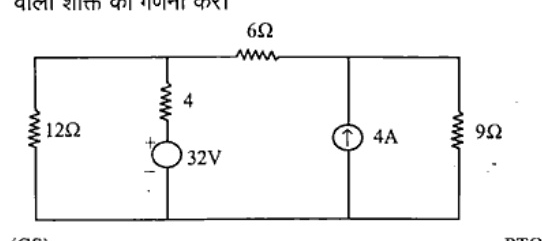
7 MarksbCompute the power dissipated in $9\Omega$ resistor using superposition theorem.
How to answer
- Case 1: Activate 32V voltage source only (open circuit the 4A current source) and calculate current $I'$ through $9\Omega$
- Case 2: Activate 4A current source only (short circuit the 32V voltage source) and calculate current $I''$ through $9\Omega$
- Calculate total current through $9\Omega$: $I = I' + I''$ taking directions into account
- Compute power dissipated: $P = I^2 \times 9$
-
7 MarksaDiscuss about the real power, reactive power, apparent power and power factor as regards to AC circuit.
How to answer
- Definitions and expressions for Real Power ($P = VI\cos\phi$, Watts)
- Reactive Power ($Q = VI\sin\phi$, VAR)
- Apparent Power ($S = VI$, VA)
- Power Factor definition ($\cos\phi = P/S$)
- Power triangle diagram showing relationship $S^2 = P^2 + Q^2$
-
7 MarksbIf the power consumed in a $3-\phi$, 220V, 50Hz supply. What will be power consumed if the same load is connected in star. Also calculate the phase and line quantities of both the cases. The power factor of the load is 0.8 lagging.
How to answer
- Assume delta connection as the initial condition consuming power $P_\Delta$
- Determine relationship between star and delta powers: $P_Y = \frac{1}{3} P_\Delta$
- Calculate line and phase voltages for delta ($V_{ph} = V_L = 220\text{ V}$) and star ($V_{ph} = V_L/\sqrt{3} = 127\text{ V}$)
- Calculate line and phase currents for both star and delta connections in terms of impedance $Z_{ph}$ or given power
-
7 MarksaDraw Phasor diagram of a 3-phase star connected load and find the relation between phase and line voltages and currents.
How to answer
- Schematic diagram of star-connected system
- Derivation showing $I_L = I_{ph}$
- Derivation of line voltage: $V_{RY} = V_R - V_Y$, using phasor geometry to show $V_L = 2 V_{ph} \cos(30^\circ) = \sqrt{3} V_{ph}$
- Neat phasor diagram showing phase voltages, line voltages, and current vectors
-
7 MarksbA delta connected load has a parallel combination of resistance ($2\Omega$) and capacitive resistance ($-j5\Omega$) in each phase. If a balanced three phase 440V supply is applied between lines, find the phase currents and line currents and the phasor diagram.
How to answer
- Calculate phase impedance: $Z_{ph} = \frac{2 \times (-j5)}{2 - j5} = \frac{-j10}{2-j5} = \frac{10\angle-90^\circ}{\sqrt{29}\angle-68.2^\circ}$
- Calculate phase voltage: $V_{ph} = V_L = 440\text{ V}$
- Compute phase currents: $I_{ph} = 440 / |Z_{ph}|$
- Calculate line currents: $I_L = \sqrt{3} I_{ph}$
- Draw phasor diagram showing line voltages, phase currents, and line currents
-
7 MarksaDerive an expression for an energy density in magnetic circuits.
How to answer
- Define magnetic energy stored: $W = \int e i \, dt = \int L i \, di = \frac{1}{2} L I^2$
- Substitute inductance $L = \frac{N^2 \mu A}{l}$ and magnetic field intensity $H = \frac{N I}{l}$
- Derive total energy: $W = \frac{1}{2} (\mu H^2) (A l) = \frac{1}{2} B H \times \text{Volume}$
- Obtain energy density: $w_f = \frac{W}{\text{Volume}} = \frac{1}{2} B H = \frac{B^2}{2\mu}$
-
7 MarksbExplain the principle of operation of 3-phase induction motor.
How to answer
- Production of rotating magnetic field (RMF) of constant magnitude ($1.5 B_m$) rotating at synchronous speed $N_s = \frac{120f}{P}$
- Induction of EMF in short-circuited rotor conductors by Faraday's law
- Flow of rotor current and development of electromagnetic torque ($T \propto B I_r \cos\phi_2$)
- Application of Lenz's law causing rotor to follow the rotating magnetic field
- Explanation of why rotor never reaches synchronous speed (concept of slip)
-
7 MarksaWhat are the necessary tests to determine the efficiency, voltage regulation and temperature rise of winding and insulation of transformer?
How to answer
- Open Circuit (OC) test: to determine core losses and shunt branch parameters for efficiency
- Short Circuit (SC) test: to determine full load copper losses and equivalent series impedance for regulation and efficiency
- Formulas for efficiency ($\eta$) and voltage regulation using OC and SC test data
- Sumpner's (Back-to-Back) test: purpose and procedure to determine maximum temperature rise of winding and insulation under full-load conditions without consuming full power
-
7 MarksbA 1100/400V, 50Hz single phase transformer has 100 turns on the secondary winding. Calculate the number of turns on its primary.
How to answer
- State transformation ratio formula: $\frac{V_1}{V_2} = \frac{N_1}{N_2}$
- Substitute values: $\frac{1100}{400} = \frac{N_1}{100}$
- Solve for $N_1$: $N_1 = 100 \times \frac{1100}{400} = 275\text{ turns}$
-
7 MarksaDefine the following with suitable diagram: i) RMS values ii) Form factor iii) Peak factor
How to answer
- Definition and heating-effect concept of RMS value with mathematical expression: $V_{rms} = \sqrt{\frac{1}{T}\int_0^T v^2(t) dt} = \frac{V_m}{\sqrt{2}}$
- Definition of Form Factor: $k_f = \frac{\text{RMS value}}{\text{Average value}} = 1.11$ (for sine wave)
- Definition of Peak Factor (Crest Factor): $k_p = \frac{\text{Peak value}}{\text{RMS value}} = 1.414$ (for sine wave)
- Neat diagram of an AC sinusoidal wave showing peak, average, and RMS values
-
7 MarksbA transformer that with a 120 volt primary and 12 volts in the secondary and a primary with 900 turns of wire, how many turns would be required in the secondary?
How to answer
- State transformer turns ratio equation: $\frac{N_2}{N_1} = \frac{V_2}{V_1}$
- Substitute values: $N_2 = N_1 \times \frac{V_2}{V_1} = 900 \times \frac{12}{120}$
- Calculate result: $N_2 = 90\text{ turns}$
-
7 MarksaExplain the torque-speed characteristic and speed control of separately excited DC motor.
How to answer
- Derivation of speed equation: $N = \frac{V - I_a R_a}{k \Phi}$ and torque equation $T = k \Phi I_a$
- Torque-speed equation: $\omega = \frac{V}{k\Phi} - \frac{R_a}{(k\Phi)^2} T$
- Sketch of torque-speed characteristic curve showing droop due to armature resistance drop
- Speed control methods: Armature voltage control (below rated speed) and Field flux control (above rated speed)
-
7 MarksbExplain principle of operation and characteristics of BJT.
How to answer
- Basic structure and working principle of BJT (npn/pnp) with forward-biased emitter-base and reverse-biased collector-base junctions
- Carrier flow and current relationship: $I_E = I_B + I_C$
- Common Emitter (CE) configuration input characteristics ($I_B$ vs $V_{BE}$)
- Common Emitter output characteristics ($I_C$ vs $V_{CE}$) showing active, saturation, and cutoff regions
-
14 MarksWrite short notes on: (any two) a) Voltage Regulation b) Types of losses occurring in electrical machines c) Logic Gates d) Half and full adder circuits
How to answer
- Voltage Regulation: definition, formula $\%VR = \frac{V_{NL} - V_{FL}}{V_{FL}} \times 100$, importance in power systems and transformers
- Losses in Electrical Machines: copper losses ($I^2 R$), core/iron losses (hysteresis and eddy current losses), mechanical losses (friction and windage)
- Logic Gates: basic gates (AND, OR, NOT), universal gates (NAND, NOR), and exclusive gates (XOR, XNOR) with truth tables and symbols
- Half and Full Adders: logic diagrams, Boolean equations for Sum and Carry, truth tables
Go to where you left off?
Quick Add to Notes
Save questions, your own notes and screenshots into notes filed by unit. It takes a free account.
Create free accountHave an account? Log in
Notes Panel